SD1 Series Inverters Function Parameters
-55-
Name Description Default Modify
0.1%~10.0%
Setting range of P04.02: 0.0%~50.0%
P04.03
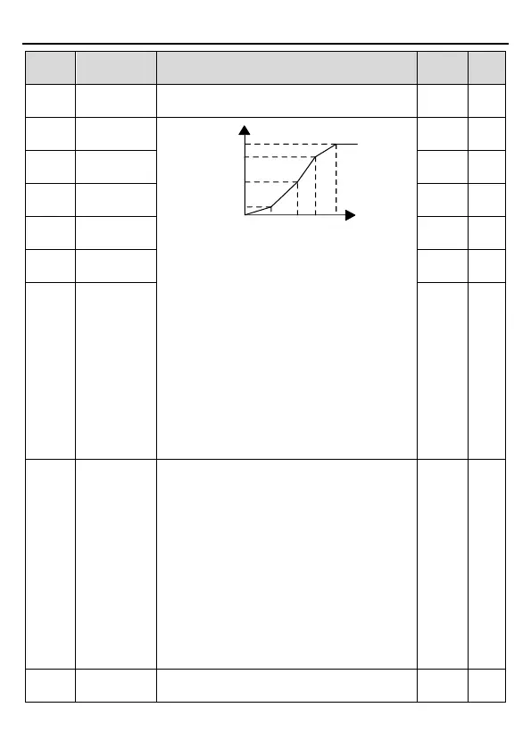
Output voltage
Output
frequency
V1
V2
V3
f1 f2 f3
100.0%
b
f
b
V
When P04.00
=1, the user can set V//F curve
through P04.03~P04.08.
V/F is generally set according to the load of the
motor.
Note:
V1<V2<V3, f1<f2<f3. Too high low
frequency voltage will heat the motor excessively
or damage. Overcurrent stall or overcurrent
protection may occur.
Setting range of P04.03: 0.00Hz~P04.05
Setting range of P04.04, P04.06 and P04.08:
0.0%~110.0% (rated motor voltage)
Setting range of P04.05: P04.03~P04.07
Setting range of P04.07: P04.05~P02.02 (rated
0.00Hz ○
P04.04
V/F voltage
0.0% ○
P04.05
0.00Hz ○
P04.06
V/F voltage
0.0% ○
P04.07
0.00Hz ○
P04.08
V/F voltage
point 3
0.0% ○
P04.09
V/F slip
gain
This function code is used to compensate the
change of the rotation speed caused by load
during compensation SVPWM control to improve
the rigidity of the motor. It can be set to the rated
slip frequency of the motor which is counted as
below:
△f=f
b
-n*p/60
Of which, f
b
is the rated frequency of the motor,
its function code is P02.02; n is the rated rotating
speed of the motor,
P02.03
; p is the pole pair of the motor. 100.0%
corresponds to the rated slip frequency△f.
Setting range: 0.0~200.0%
100.0% ○
P04.10
In the SVPWM control mode, current fluctuation
may occur to the motor on some frequency,
10 ○