SD1 Series Inverters Function Parameters
-89-
Name Description Default Modify
P10.06 Preset speed 2
value means reverse rotation.
P10.04
P10.02
P10.03
P10.05 P10.07
P10.06
P10.31 P10.33
P10.32
ACC time
2 stages
DEC time
2 stages
P10.30
P10.28
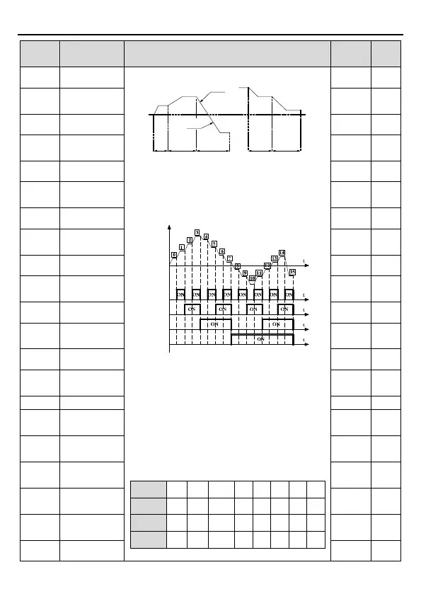
Preset speeds are in the range of --f
max
~f
max
and
it can be set continuously.
SD1 series inverters
selected by the combination of Preset terminals
1~4, corresponding to the speed 0 to speed 15.
Output frequency
Terminal 1
(16)
Terminal 2
(17)
Terminal 3
(18)
Terminal 4
(19)
When S1=S2=S3=S
4=OFF, the frequency input
manner is selected via code P00.06 or P00.07.
When all terminals aren't off, it runs at Preset
which takes precedence of keypad, analog
value, high-speed pulse, PLC, communication
frequency input. Select at most 16 steps speed
via the combination code of S1, S2, S3, and S4.
The start-up and stopping of Preset running are
determined by function code P00.06
relationship between S1, S2, S3, S4 and Preset
speed is as following:
erminal
OFF
ON OFF ON
ON
ON
erminal
OFF
OFF
ON ON
ON ON
erminal
OFF
OFF
OFF OFF
ON
ON
ON ON
ermin
OFF
OFF
OFF OFF
OFF
0.0%
○
P10.07
Running time
0.0s
○
P10.08 Preset speed 3
0.0%
○
P10.09
Running time
0.0s
○
P10.10 Preset speed 4
0.0%
○
P10.11
0.0s
○
P10.12 Preset speed 5
0.0%
○
P10.13
0.0s
○
P10.14 Preset speed 6
0.0%
○
P10.15
0.0s
○
P10.16 Preset speed 7
0.0%
○
P10.17
Running time
0.0s
○
P10.18 Preset speed 8
0.0%
○
P10.19
Running time
0.0s
○
○
P10.21
Running time
0.0s
○
P10.22
0.0%
○
P10.23
Running time
0.0s
○
P10.24
0.0%
○
P10.25
Running time
0.0s
○
P10.26 Preset speed
0.0%
○