Chapter 4 Parts 69
Control Kit - Radio Remote (90715572) (see "Control Kit, Radio Remote (90715572)" on page
68)
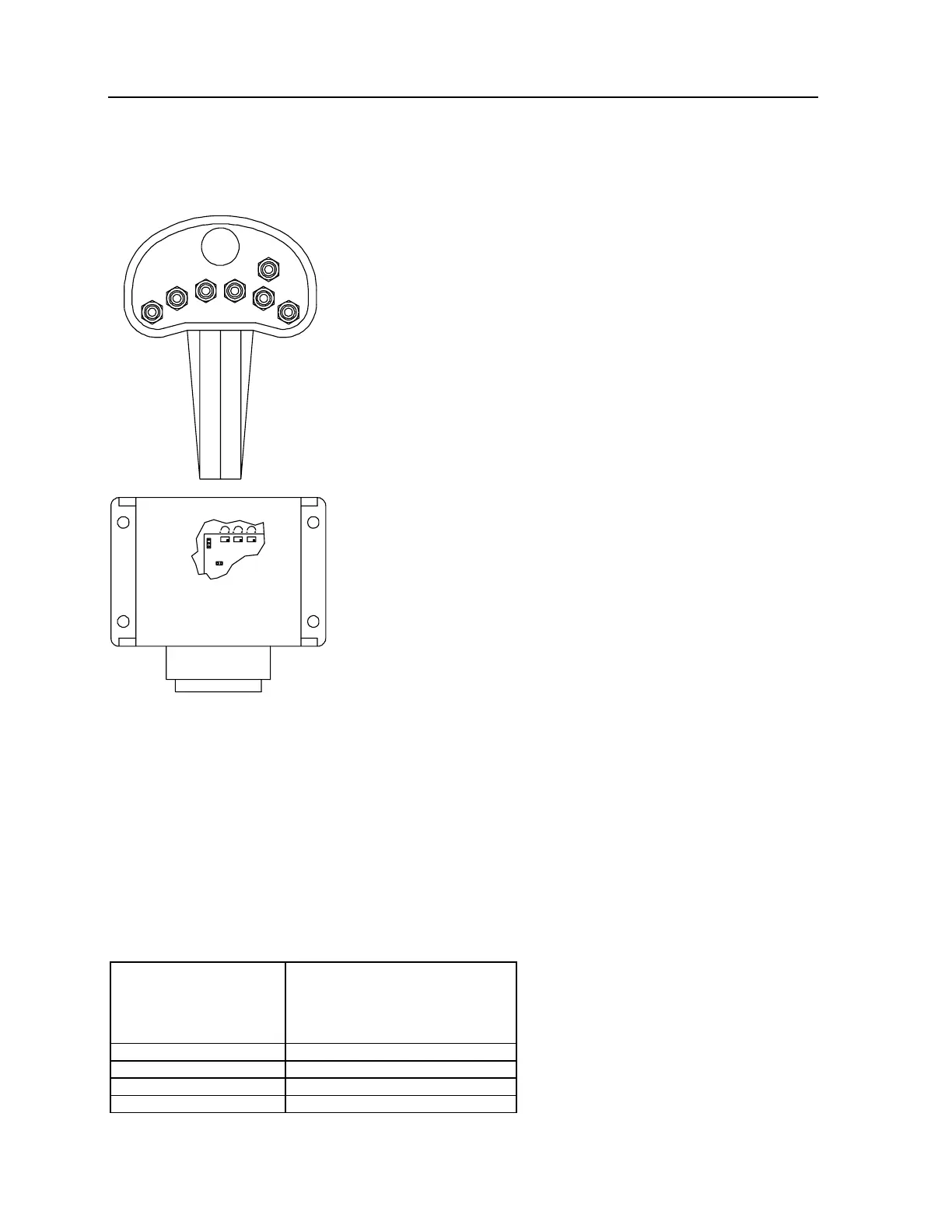
JUMPER CONNECTIONS INSIDE RECEIVER
J1: PULSE/DITHER FREQUENCY
- NO JUMPER
J2: CONTROL RANGE OF OUTPUT CURRENT
(ONLY CURRENT-CONTROL)
- PIN 2/3 CONNECTED: 0 - 2A
- ALL SWITCHES ARE MOMENTARY
UNLATCHED TYPE
- LABEL HANDSET AS SHOWN
J2
J1
3
2
1
1 2
P3 P2 P1
ENGINE
START
STOP
C
O
M
P
R
E
S
S
O
R
L
O
W
E
R
D
N
U
P
W
I
N
C
H
D
N
U
P
E
X
T
I
N
O
U
T
R
O
T
A
T
E
C
C
W
C
W
O
P
T
I
O
N
P1: TRIMMING POTENTIOMETER FOR MAXIMUM VALUES:
On transmitter handle, engage rotation CW or CCW function switch and pull trigger fully on. Crane
may or may not
begin to move at this time due to P1 initial setting.
P2: TRIMMING POTENTIOMETER FOR INITIAL VALUE ADJUSTMENT:
On transmitter, engage rotation CW or CCW function switch without pulling trigger. Adjust P2 counterclockwise until
crane begins to move. At this time, adjust P2 clockwise until no movement is detected. Slightly engage trigger and
adjust P2 to fine tune.
P3: TRIMMING POTENTIOMETER TO ADJUST DITHERAMPLITUDE:
Adjust clockwise or counterclockwise for smoothness or operation.
Control Kit - Radio
Remote (90715572)
(see
"Control Kit, Radio
Remote (90715572)" on
page 68)A1
ROT CW
A2 EXT OUT
A3 WINCH DN
A4 WINCH UP
A5 PROP VALVE +
 Loading...


