INFICON Description | 4
UL6000-Fab,-PLUS-Operating-instructions-iinc75en1-01-(2206) 29 / 152
4.3.3 Vacuum connections
4.3.3.1 Inlet
The inlet is located on the upper part of the device. It is a DN63 flange. If necessary,
use a suitable reducer to connect the specimen to the inlet flange. An adapter DN63
ISO-K/DN40 ISO-KF is included in the scope of delivery.
If you select the vacuum leak test mode, connect the test object or the vacuum
chamber to the flange. See also "Connect recipient/test object to inlet flange [}47]".
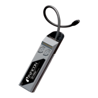
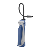
Use the inlet for connecting the sniffer line SL200, too.
NOTICE
If you use a filter, for example a centering ring with wire mesh, to prevent dust or dirt
accumulation at the inlet of the leak detector:
► Note that ice can form on filters due to condensation of water vapor. This can lead
to property damage.
4.3.3.2 Exhaust
WARNING
Danger of poisoning due to harmful gases
Depending on the connected container and the gas contained therein, harmful gases
can get into the ambient air via the exhaust filter of the leak detector.
► Make sure you have protection measure to prevent inhaling hazardous gases.
► Do not pump out toxic, corrosive, or explosive gases that create a hazard.
► Connect an exhaust hose. The exhaust gas connection must be continuously
connected to an exhaust gas system and must not be closed.
The exhaust is located on the lower side of the device. The exhaust is a tubular
connection with internal and external thread. To connect the exhaust hose adapter
see also “Connect the supplied accessories [}43]“.

 Loading...