EasyManuals Logo

Inovance SV660P Series User Manual

Inovance SV660P Series
156 pages
To Next Page IconTo Next Page
To Previous Page IconTo Previous Page
Page #107 background imageLoading...
Page #107 background image
Wiring
106
Note
Store the battery in environments compliant with the required temperature range
and ensure reliable contact and sufficient battery power. Failure to comply may
result in encoder data loss.
Model of the battery box (battery included): S6‑C4
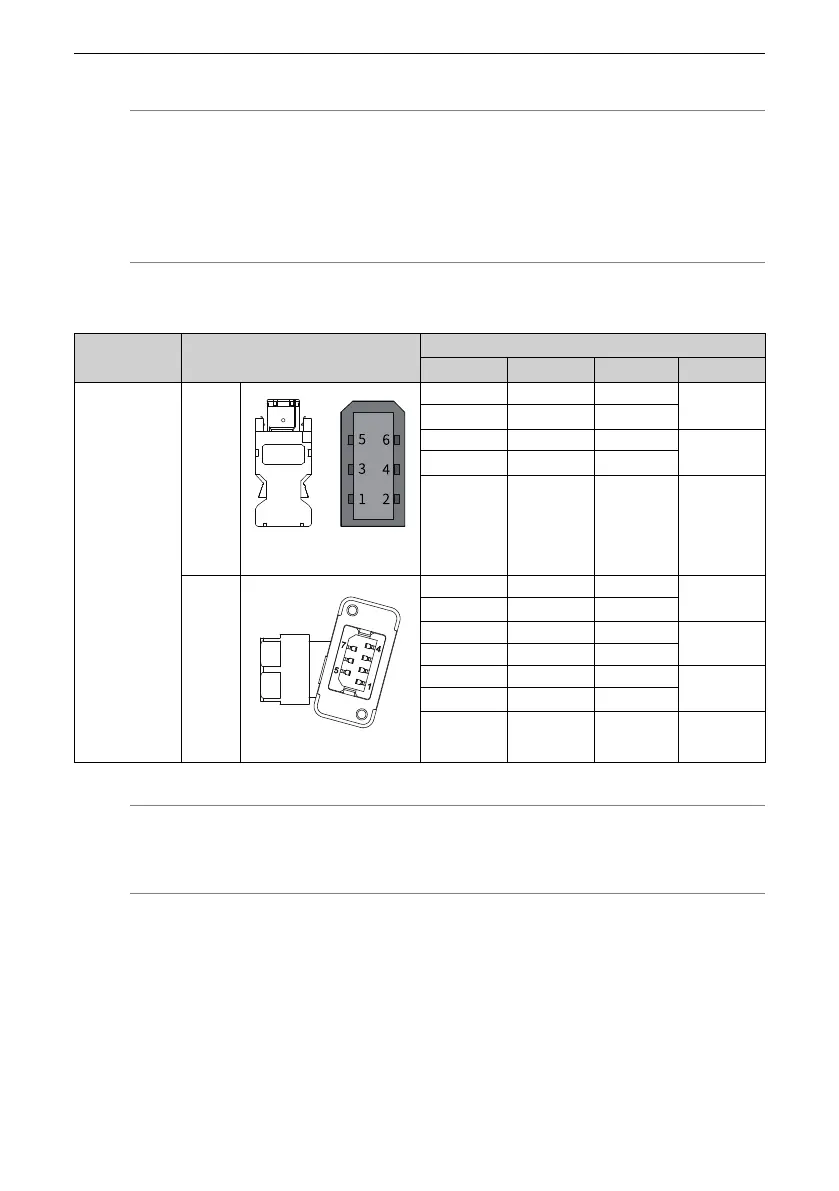
Table 3–27 Terminal‑type motor encoder cable connector
Applicable Motor
Flange Size
[1]
Outline Drawing of the Connector
Terminal Pin Layout
Pin No.
Signal Name
Color
Type
Terminal‑type
motor:
40
60
80
Servo
drive side
6‑pin male (The joint face is on
the right side.)
1 +5V Red
Twisted pair
2 GND
Orange
5 PS+ Blue
Twisted pair
6 PS‑
Purple
Enclosure PE
Motor
side
7‑pin connector
1 PS+ Blue
Twisted pair
2 PS‑
Purple
3 DC+ Brown
Twisted pair
4 DC‑ Black
5 +5V Red
Twisted pair
6 GND
Orange
7 PE
Note
[1] The flange size refers to the width of the mounting flange.

Table of Contents

Questions and Answers:

Question and Answer IconNeed help?

Do you have a question about the Inovance SV660P Series and is the answer not in the manual?

Inovance SV660P Series Specifications

General IconGeneral
Model/SeriesSV660P Series
CategoryServo Drives
Protection ClassIP20
Output Power7.5kW
Control ModeTorque, Speed, Position
Communication ProtocolCANopen, Modbus
Encoder FeedbackIncremental encoder, Absolute encoder
SafetySTO (Safe Torque Off)
Protection FeaturesOvervoltage, Undervoltage, Overcurrent, Overtemperature, Encoder error
Ambient Temperature0°C to 55°C
Humidity5% to 95% (non-condensing)
Vibration Resistance5.9 m/s²
Installation AltitudeUp to 1000m above sea level
Cooling MethodNatural cooling

Related product manuals