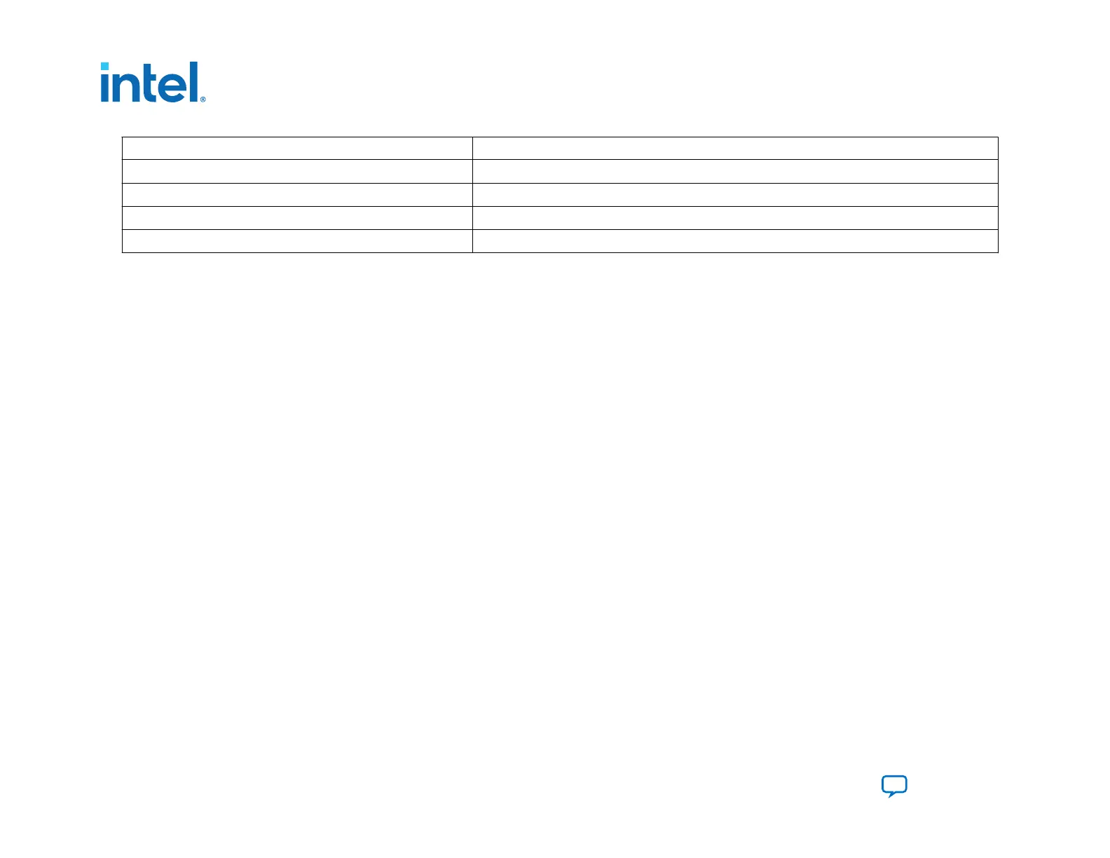
CFI Device (Megabit) Address Range
128
0x0000000–0x0FFFFFF
256
0x0000000–0x1FFFFFF
512
0x0000000–0x3FFFFFF
1024
0x0000000–0x7FFFFFF
3.1.7.2. Designing with the PFL II IP Core for Avalon-ST Single Device Configuration
This section describes the procedures on how to use the PFL II IP core.
To target a MAX II, MAX V, or Intel MAX 10 device requires the use of Intel Quartus Prime Standard Edition whereas targeting
a Intel Agilex requires Intel Quartus Prime Pro Edition.
The process of creating the Avalon-ST single device configuration design targeting a MAX10/MAX V/MAX II device involves
three steps.
1. Generate the AVST design for the MAX device with the default option address.
2.
Create the Intel Agilex .pof file in setting the appropriate option bits.
3.
Regenerate the Parallel Flash Loader II Intel FPGA IP (PFL II) with the option bits used to generate the Intel Agilex .pof
file and recompile the Intel MAX 10 design.
You can find an Intel MAX 10 system design example that implements the PFL II IP for AVST x32 configuration mode in the
installer package of the Intel Agilex F-Series Transceiver-SoC Development Kit.
3. Intel Agilex Configuration Schemes
683673 | 2021.10.29
Intel
®
Agilex
™
Configuration User Guide
Send Feedback
76
 Loading...


