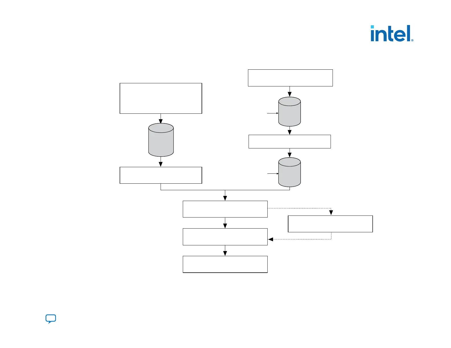
Figure 26. Process for Using the PFL IP Core
Figure shows the process for using the PFL IP core, using MAX II as an example.
Create a new MAX II design,
instantiate the PFL Megafunction in
the MAX II design, and create
Pin Assignments
Add the MAX II .pof to the
Quartus Prime Programmer
Add the flash .pof in the
Quartus Prime Programmer
Program the MAX II and Flash Devices
MAX II configures the FPGA with the
configuration data from the Flash Device
Compile and
obtain the
FPGA
.sof(s)
Convert to
.pof for the
Targeted
Flash
Compile
and obtain
MAX II
.pof
Add the .sof(s) for conversion to .pof
Create new FPGA
designs
Create the optional Jam
programming file
3. Intel Agilex Configuration Schemes
 Loading...


