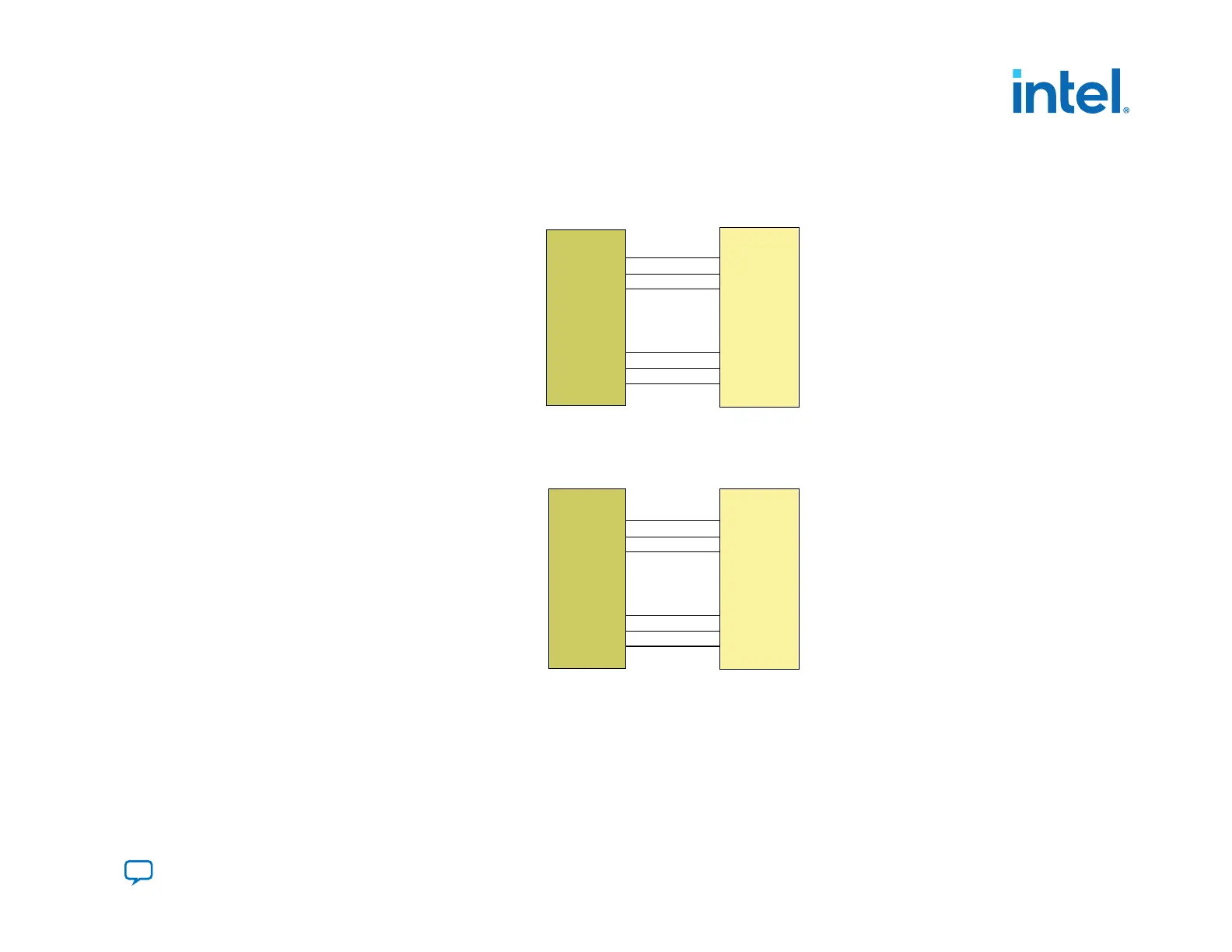
Figure 29. Flash Memories in 16-Bit Mode
The flash memory addresses in 16-bit flash memory shift one bit down in comparison with the flash addresses in PFL II IP core. The flash address in the flash
memory starts from bit 1 instead of bit 0.
22
21
20
-
-
-
2
1
0
address: 23 bits
23
22
21
-
-
-
3
2
1
address: 23 bits
PFL II
Flash Memory
Figure 30. Cypress and Micron M28, M29 Flash Memory in 8-Bit Mode
The flash memory addresses in Cypress 8-bit flash shifts one bit up. Address bit 0 of the PFL II IP core connects to data pin D15 of the flash memory.
23
22
21
-
-
-
2
1
0
address: 24 bits
22
21
20
-
-
-
1
0
D15
address: 24 bits
PFL II
Flash Memory
3. Intel Agilex Configuration Schemes
683673 | 2021.10.29
Send Feedback
Intel
®
Agilex
™
Configuration User Guide
85
 Loading...


