EasyManua.ls Logo

Intel Xeon Phi Processor x200 User Manual

Intel Xeon Phi Processor x200
114 pages
To Next Page IconTo Next Page
To Previous Page IconTo Previous Page
Page #73 background image
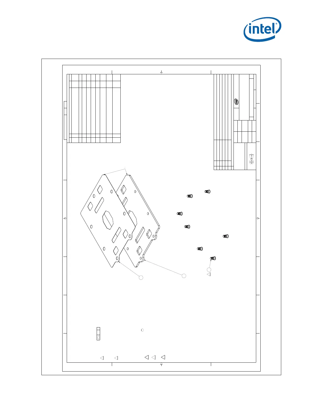
Figure E-1. Backplate Assembly, 1/3
13
4
5678
B
C
D
A
123
4
5678
B
C
D
A
2200 MISSION COLLEGE BLVD.
P.O. BOX 58119
SANTA CLARA, CA 95052-8119
R
.24 A
H77469 1 09
DWG. NO SHT. REV
SHEET 1 OF 3
DO NOT SCALE DRAWING
SCALE: 2:1
09H77469D
REV
DRAWING NUMBER
SIZE
KNL BACKPLATE ASSY
TITLE
DEPARTMENT
SEE NOTESSEE NOTES
FINISHMATERIAL
-
DATEAPPROVED BY
08/14/13
DATECHECKED BY
08/14/13
DATEDRAWN BY
08/14/13
DATEDESIGNED BY
DIMENSIONS ARE IN MILLIMETERS
THIRD ANGLE PROJECTION
PARTS LIST
DESCRIPTIONPART NUMBER
ITEM NO
QTY
KNL BACK PLATE ASSEMBLYH77469-002TOP
KNL BACK PLATEG93719-00211
KNL BACK PLATE STUDH12853-00427
KNL BACK PLATE INSULATORG93724-00231
REVISION HISTORY
ZONE REV DESCRIPTION DATE APPR
- 01 TOOLING RELEASE 03/26/15
PG2 7-C
PG2 6-A
02
1. ADDED DATUM B
2. FIXED GD & T DIMENSION CALL OUT
4/1/15
03
1. UPDATED REV ON PART TO MATCH DRAWING.
2. ADDED SHEET 4 FOR BOLSTER PLATE AND MATERIAL CALLOUT.
3. ADDED NOTE 9.
4/15/15
PG2 7A
04
1. ADDED NOTE 9 TO CALL OUT CRITICAL TO FUNCTION DIMENSIONS.
2. REINSTATED DRAWING G93719 AND REMOVED SHEET 4.
3. CHANGED DIMENSION TOLERANCE RANGE.
5/7/15
PG2 6A 05
1. REMOVED PLATE THICKNESS CRITICAL TO FUNCTION CALLOUT,
SHOWN ON BOLSTER PLATE DRAWING.
6/29/15
PG1 7C 06
1. UPDATED NOTE 4 TO LOWER THE PULLOUT FORCE FROM 1110N TO 267N.
2. ADDED NOTE 10 AND 11.
9/1/15
PG2 A3
PG2 B2
PG1 B8
PG1 C7
07
1. CHANGED TRUE POSITION TOLERANCE FROM 0.1 TO 0.15
2. REMOVED THE PROFILE TOLERANCE DIMENSION. USE NOTE 2.
3. ADDED NOTE 12
4. REMOVED NOTE 5 WORDING.
10/20/15
PG2 B6 08
1. OVERALL STUD DIMENSION CHANGED FROM 6.334 TO 6.80
2. ROLLED PART NUMBER FROM H77469-001 TO H77469-002.
2/11/16
PG1 A3
PG2 A3
PG3 D6
PG3 B3
PG1 A3
PG1 C7
09
1. REMOVED DATUM B AND UPDATED NOTE 2 TO REFLECT THE CHANGE.
2. REMOVED CTF DIMENSION
3. ADDED CTF DIMENSION
4. REMOVED THE WORD "PRODUCTION" FROM THE ASSEMBLY
5. UPDATED PART NUMBER TABLE FOR THE STUD FROM -003 TO -004.
6. MODIFIED NOTE 3C TO REMOVE THE PART NUMBER REVISION.
7/18/16
NOTES; UNLESS OTHERWISE SPECIFIED:
1. REFERENCE DOCUMENTS
ASME Y14.5M-2009 - STANDARD DIMENSION AND TOLERANCES
164997 - INTEL MARKING STANDARD
2. FEATURES NOT SPECIFIED ON DRAWING SHALL BE CONTROLLED BY
3D CAD DATABASE. FOR FEATURES NOT EXPLICITLY TOLERANCED:
(BASIC DIMENSION FROM 3D CAD MODEL):
3 MARK ASSEMBLY PART APPROXIMATELY WHERE SHOWN PER
INTEL MARKING STANDARD (G14577) WITH ADDITIONAL
INFORMATION:
A) ASSEMBLY VENDOR ID
B) DATE CODE
C) INTEL PART NUMBER
4 ATTACH STUDS:
- PULL OUT FORCE > 667N (150 LBF)
- TORQUE OUT > 2.25N-m (20 IN-LBF)
- FAILURE MODES: STUDS (7) MUST NOT SHEAR, DEFORM,
STRIP, CRACK, OR TORQUE-OUT BELOW TORQUE LIMIT.
5. NOT USED
6. CLEAN AND DEGREASE BACKPLATE ASSEMBLY BEFORE ATTACHING
INSULATION.
7. AFTER APPLICATION THE INSULATOR MUST BE FREE OF BUBBLES,
POCKETS, CREASES, AND ANY OTHER DEFORMATIONS.
8. FINAL ASSEMBLY SHALL BE FREE OF OIL AND DEBRIS.
9. DIMENSIONS MARKED ARE CRITICAL TO FUNCTION
DIMENSIONS (CTF).
10 INSTALL ALL STUDS FLUSH TO THIS SURFACE, NOT PROTRUDING
BEYOND BACKPLATE SURFACE.
11 BACKPLATE ASSEMBLY TO BOLSTER PLATE ASSEMBLY (H77470)
STUD/NUT MUST BE ABLE TO ENGAGE WITH MOTHERBOARD THICKNESS'
IN THE RANGE OF 1.42MM-2.69MM (0.056"-0.106").
12 FLATNESS MUST BE MEASURED IN THE UNCONSTRAINED STATE. ALL
OTHER CTF MEASUREMENTS CAN BE MEASURED IN THE CONSTRAINED
STATE.
4
7X
2
1
3
USE PIN 1 CHAMFER FOR ORIENTATION OF INSULATOR TO BACK PLATE
C
Order Number: 334785-002 Intel
®
Xeon
®
Phi™ Processor x200 Product Family TMSDG
73
Retention Assembly Mechanical Drawings

Table of Contents

Question and Answer IconNeed help?

Do you have a question about the Intel Xeon Phi Processor x200 and is the answer not in the manual?

Intel Xeon Phi Processor x200 Specifications

General IconGeneral
ArchitectureKnights Landing
Process Technology14nm
Base Clock Speed1.3 GHz - 1.5 GHz
Turbo Boost Clock Speed1.7 GHz
Memory SupportDDR4
Max Memory384 GB
Memory Speed2400 MHz
Memory Channels6
Integrated Memory ControllerYes
Instruction Set ExtensionsAVX-512
PCI Express Lanes36
SocketLGA 3647
TDP215 W
L1 Cache32 KB per core

Summary

Processor Mechanical Design

2.1 Processor Package Mechanical Specifications

Overview of processor package mechanical design and integration, serving as the primary interface.

2.2 Processor Package Description

Details the multi-chip package, including LGA3647-1 socket interface and IHS.

2.3 Package Mechanical Dimensions

Provides processor package dimensions and tolerances, including IHS and fabric extension details.

2.3.1 Package Critical-to-Function Attributes

Lists package land dimension details, base material, plating and plating thickness.

Socket Mechanical Design

3.1 LGA3647-1 Socket Overview

Describes the SMT LGA socket for the processor, its components, and features.

3.1.1 Socket Features

Lists LGA3647-1 socket attributes, including pin grid geometry and solder ball characteristics.

3.1.2 Socket Mechanical Requirements

Details socket attachment methods and testing against mechanical shock and vibration.

3.1.2.2 Socket Loading and Deflection Specifications

Provides loading and board deflection specs for the LGA3647-1 socket.

3.2 Socket Critical-to-Function Interfaces

Lists CTF attributes for main board layout and component interface to the socket.

3.3.3 Socket-Package Contact Characteristics

Details contact count, layout, base material, plating, and paddle specifications.

3.3.3.1 Contact/Pad Mating Location

Defines offset between LGA land center and solder ball center for contact alignment.

3.3.3.2 Contact Load-Deflection Curve

Describes contact design for adequate normal force and meeting performance targets.

Retention Assembly Mechanical Design

4.1 Mechanical Retention Assembly

Describes the spring-loading mechanism for processor retention to the main board and heatsink.

4.1.1 Backplate

Details the backplate's role in structural rigidity, solder joint reliability, and material.

4.1.2 Bolster Plate with Spring

Describes the integrated subassembly with guiding posts, springs, and nuts for retention.

4.1.3 Processor Package Carrier

Details the carrier as part of PHM, its function in holding the processor and attaching to heatsink.

4.1.4 Heatsink

Specifies heatsink solution volume, material, and integration into the PHM.

4.2 Mechanical Load Specifications

Defines bolster and back plates to meet socket loading and PHM support during shock/vibration.

4.3 Heatsink Mechanical Requirements

Lists heatsink mass limits, stiffness, flatness, and base thickness attributes.

Board and System Design Guidelines

5.1 Mechanical Design Considerations

Covers retention assembly design, reference thermal solution, and validation criteria.

5.2 Printed Circuit Board (PCB) Design Considerations

Covers allowable board thickness, reference board layout, and board keep-outs.

Thermal Specifications and Design Guidelines

6.1 Thermal Specification Overview

Explains MCP thermal requirements, interface to thermal solution, and system-level cooling.

6.1.1 Thermal Design Power (TDP) and TCASE Specifications

Lists TDP and TCASE values for different processor SKUs under various workloads.

6.1.2 Case Temperature Geometry and Influence Factors

Discusses monitoring die temperatures, IHS TCASE specs, and measurement locations.

Figure 6-1. Processor Package Thermocouple Locations, Top view

Illustrates thermocouple locations on the processor package IHS for TCASE measurement.

6.1.3 Socket Maximum Temperature

Defines socket maximum temperature, via temperature guidance, and measurement methods.

6.2 Thermal Design and Management Guidelines

Covers system thermal environmental conditions, including ambient temperature and airflow.

6.2.4 Thermal Management Guidelines

Addresses compliance with TCASE targets, fan speed control, and thermal excursion power.

Quality and Reliability Requirements

A.1 Thermal/Mechanical Solution Stress Test

Details reliability performance evaluation using use conditions and acceleration models.

Related product manuals