PM43 Service Work Instructions
Intermec Proprietary Document
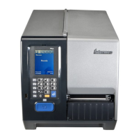
Bottom Base Print Mechanism TPH Pressure Adjust
(Does not include tear bar and screws as shown)
Printhead Pressure Adjust Assembly Replacement
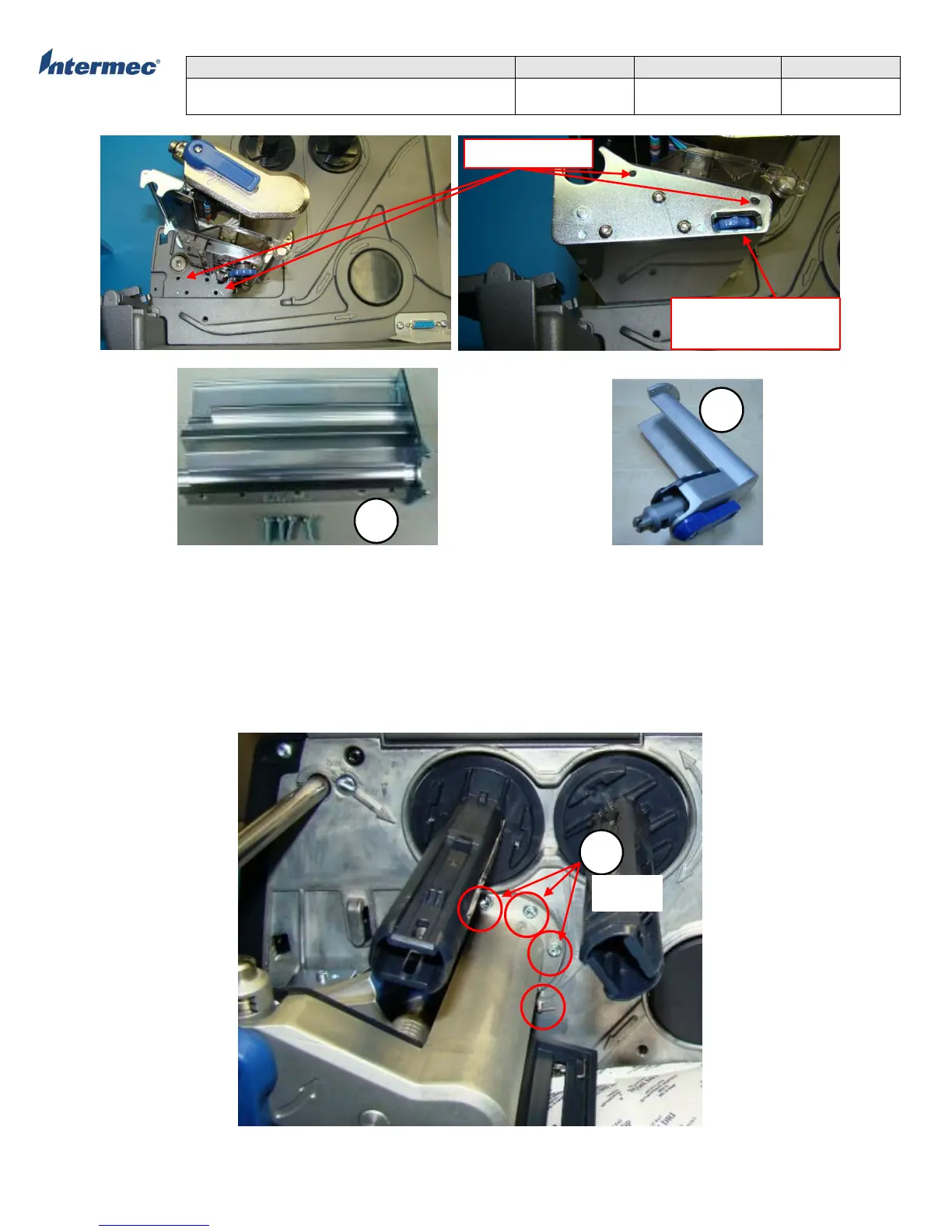
1. Turn the printhead lift lever counterclockwise to raise the printhead. See page 13 on the direction of printhead lift lever.
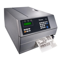
2. Remove the 5 torx screws securing the printhead pressure adjust assembly. See Figure 2 on location of torx screws.
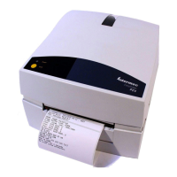
3. Prior to removing the printhead pressure adjust assembly, it is IMPORTANT to note the position of the crank lever and guide
posts. See Figure 3, Figure 4, and Figure 5.
4. Reverse the procedure for installing the replacement printhead pressure adjust assembly.
Figure 2 – Printhead Pressure Adjust Assembly
Media Guide
Adjustment lever