PM43 Service Work Instructions
Intermec Proprietary Document
This section covers the replacement of ribbon take-up mechanism. Make note of the guide pins when removing the
mechanism on the electronics side.
Tools Required
Allen Driver, 1.5mm-2.0mm
Parts Required
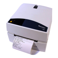
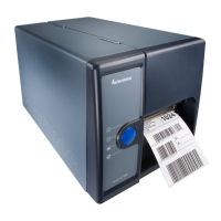
Module, Ribbon Rewind Sub, Assy Spare PM43
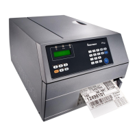
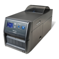
Spring,Plate1 inch Core PM43
Screw, MRT 4x8 ZP, T20, (14 lbf.in/16 kgf.cm)
Ribbon Take-up Replacement
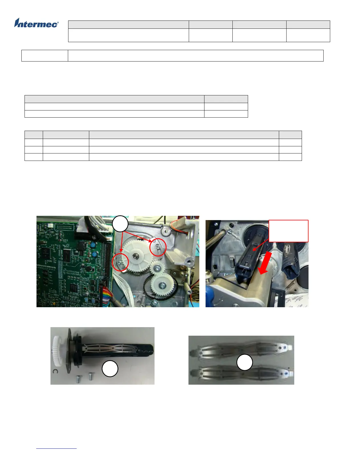
1. Remove the torx screws securing the ribbon rewind assembly module. See Figure 1.
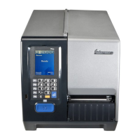
2. Remove the Allen set screw to remove the ribbon hub. See Figure 2.
3. Remove the C-clips and slide the ribbon rewind assembly toward the electronics side.
4. Reverse the procedure for re-installation.
Figure 1 Figure 2
Ribbon Rewind Assembly Module, PM43 Spring Plate, 1 Inch Core, PM43
Location of
Allen set
screw