PM43 Service Work Instructions
Intermec Proprietary Document
Media Guide Top Dancer Assembly and Dancer Assembly
This section cover the replacement of top media guide dancer assembly and the dancer assembly.
Tools Required
Parts Required
Guide,Media,Top Dancer, Assy Spare PM43
Sensor, LSS Upper Assy, Space PM43
Screw, MRT 4x8 ZP, T20, (14 lbf.in/16 kgf.cm)
Media Guide Top Dancer Assembly Replacement
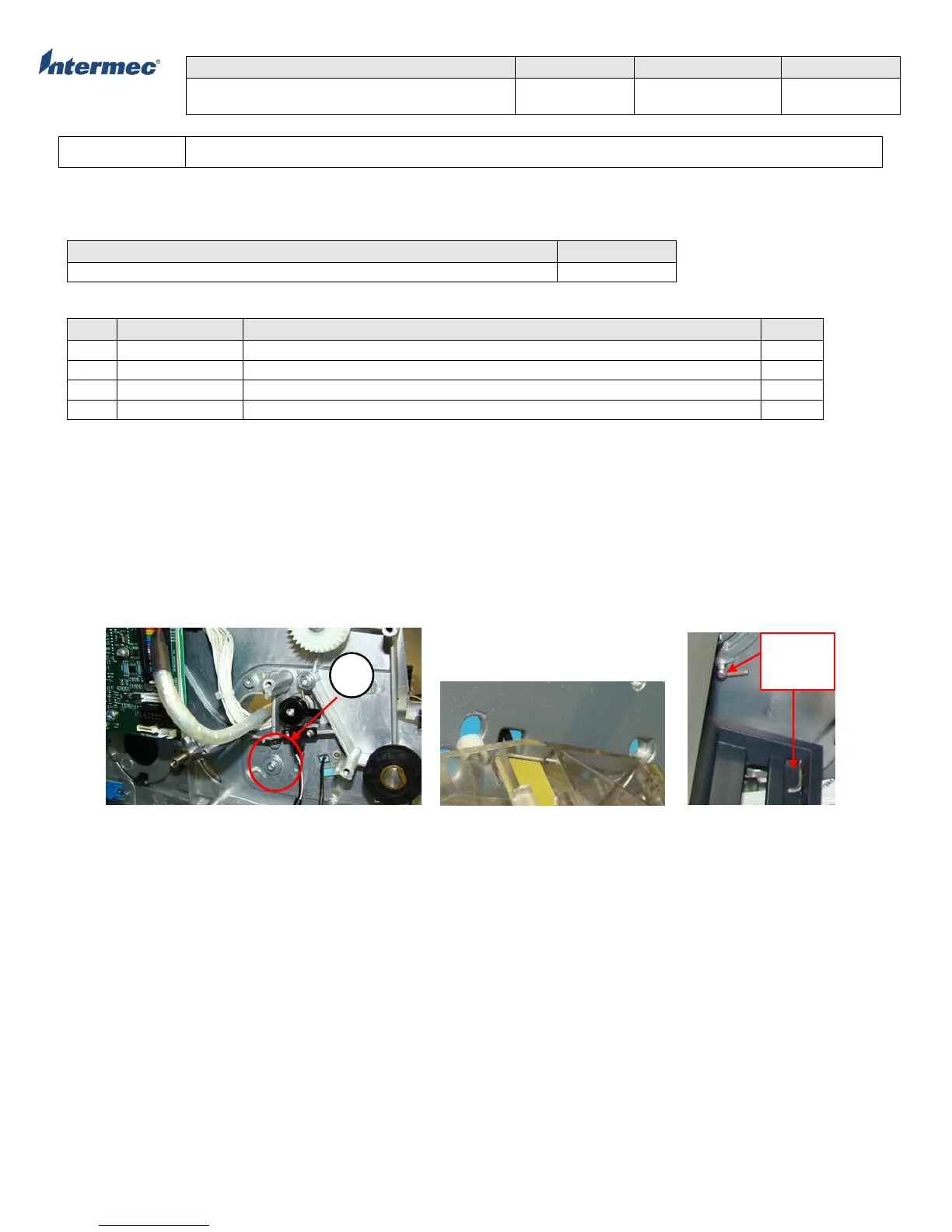
1. Remove the torx screw securing the top media guide dancer assembly from the electronic side. See Figure 1.
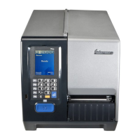
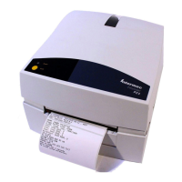
2. Disconnect the media sensor assembly from connector P20 on the main logic board (MLB) and slide the top media guide
dancer assembly away from the spine (main deck). It is IMPORTANT to note the spring position behind the spine (main deck)
guide post, guide posts, and guide pin. See Figure 2, 3, & 4.
3. For Item #3 LSS upper assembly, the assembly can be removed without having to perform Step #1. LSS upper assembly can
be removed by detaching the assembly away from the guide pin. See Figure 7.
4. For Item #2 Dancer Assembly, the assembly can be removed by removing the c-clip and slide the assembly outward. See
Figure 8.
Figure 1 Figure 2 Figure 3