PM43 Service Work Instructions
Intermec Proprietary Document
Main Logic Board (MLB) Assembly
Remove all installed interface option (RFID, Wi-Fi/Bluetooth, USB interface, parallel interface, DUART interface, etc.) board
prior to removing the MLB. See Figure 3 as a reference with all the options and connections.
Tools Required
Parts Required
PCB ASSY,MLB, Spare (include 5 Torx screws PN 1-994059-008. Does not
include grounding plate and hex standoffs)
Real Time Clock (RTC) Battery, Accessory
Screw, MRT 4x8 ZP, T20, (14 lbf.in/16 kgf.cm)
Main Logic Board (MLB) Replacement
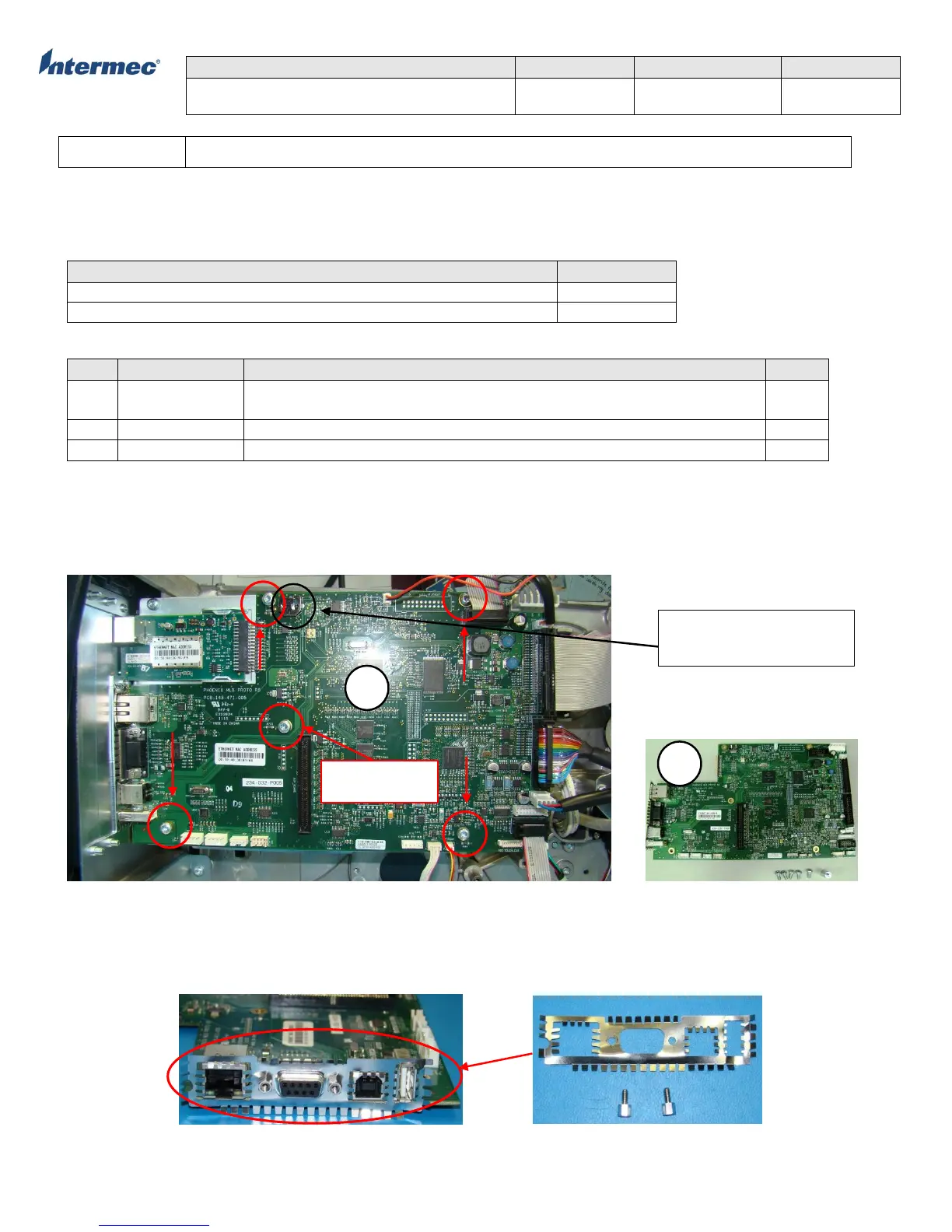
1. Remove 5 Torx screws that secure the MLB. For printer with installed option, there will be 4 Torx screws and a
standoff. See Figure 1 for reference.
2. Remove standoff for printer with installed options
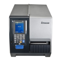
Figure 1 – Main Logic Board Spare MLB
3. Disconnect all attached cablings and carefully remove MLB away from the power supply back plate. See Figure 3.
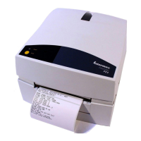
4. Remove the grounding plate and hex standoffs from the defective MLB and install onto replacement MLB. See Figure 2.
(Note: This procedure is necessary for initial built of spare MLB that did not include grounding plate and standoff)
Figure 2 MLB Grounding Plate & Hex Standoff
Optional Real-Time Clock
(RTC) Battery
Standoff with
installed option