PM43 Service Work Instructions
Intermec Proprietary Document
This section covers the replacement and installation of the print unit assembly that has several components. This section
addresses the bottom base print mechanism and the printhead adjustment assembly. The spare bottom base print mechanism
does not include the media guide assembly and sensor.
Tools Required
Parts Required
Bottom, Base Print Mech, Spare, PM43 (include 1-994059-012)
THP, Pressure Adj Assy, Spare, PM43 (complete assembly)
Screw, MRT 4x12 ZP (14 lbf.in/16 kgf.cm)
Cable, Tie, White, Locking, 4inch
Bottom Base Print Mechanism Replacement
1. Turn the printhead lift lever counterclockwise to raise the printhead. See page 13 on the direction of printhead lift lever.
2. Remove the platen roller assembly. See page 12 on how to remove the platen roller assembly.
3. Remove the drive pulley to access the torx screw underneat. See page 58 on how to remove drive pulley.
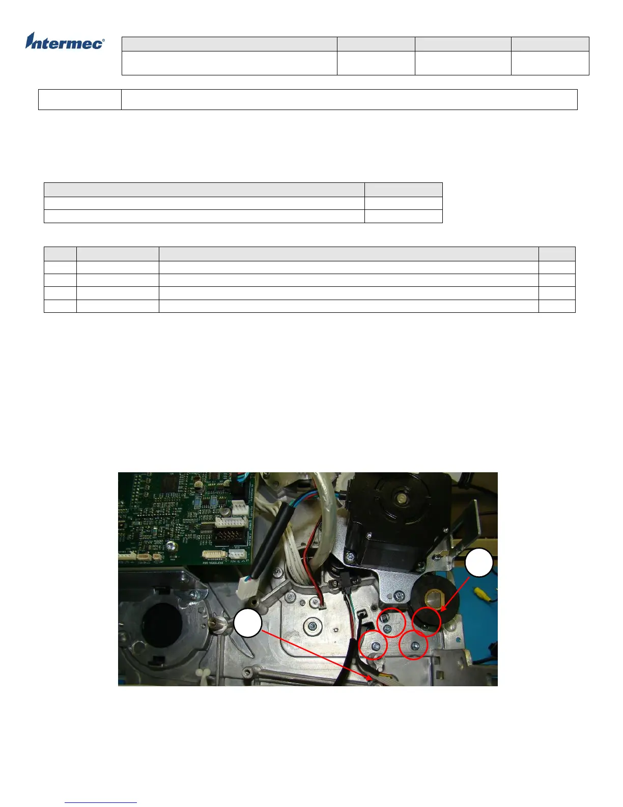
4. Remove the 4 torx screws securing the bottom base print mechanism assembly
IMPORTANT!!: Make note of the guide posts and position of media guide assembly adjustment lever as you pull the print
mechanism away from the spine (main deck). See Figure 2.
5. Remove the tear bar and reverse the procedure for installation of new print mechanism assembly
Figure 1 – Location of torx securing the print mechanism assembly