PM43 Service Work Instructions
Intermec Proprietary Document
Power Supply Electronics Assembly (Behind the MLB)
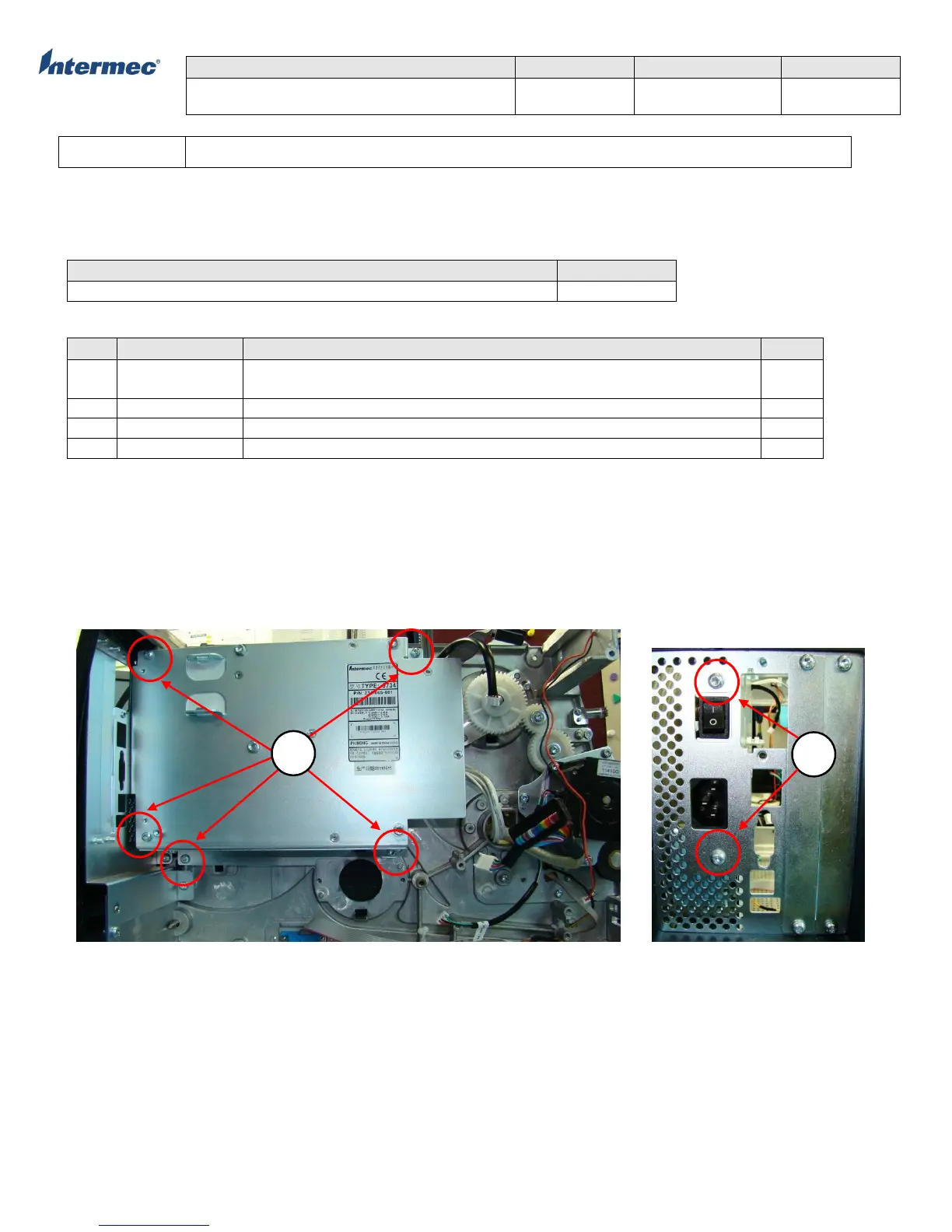
The power supply unit attaches to the spine (main deck) assembly with five torx screws and 2 torx screws on the exterior
backplane. When removing the power supply unit, note the cable routing and tie wrapping to ensure proper re-installation.
Tools Required
Parts Required
Power Supply Unit (PSU), Assy, PM43, Spare (include PSU, PSU Bracket, and
Torx screws)
Screw, MRT 4x8 ZP, T20, (14 lbf.in/16 kgf.cm)
Power Cable, Main Logic Board (MLB) – Power Supply Unit (PSU)
Cable, Tie, White, Locking, 4inch
Power Supply Unit Replacement
1. Remove the 5 torx screws with Torx driver T20 that secure the PSU onto the spine (main deck) assembly. See Figure 1
for location of the torx screws.
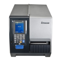
2. Remove the 2 torx screws with Torx driver T20 that secure the PSU on the back plate. See Figure 2.
3. Cutoff the tie wrap that secure the power supply unit and ribbon sensor cable. See Figure 3.
4. Reverse the procedure for re-installation.
Figure 1 Figure 2