PM43 Service Work Instructions
Intermec Proprietary Document
This section covers the replacement of front panel USB assembly. The front panel USB option is only available for PM43.
PM43c does not have this option.
To replace the USB connector, the full-touch/ICON front panel need to be removed first for PM43.
Tools Required
Parts Required
Front USB Receptacle, Cable Assembly
Screw, Plastite, M3x6, PH, Torx, T10 (3 lbf.in/3.5kgf.cm)
Front Panel USB Cable Assembly Replacement
1. Remove the front panel to access the USB cable assembly for replacement. See page 11 on how to remove the front panel.
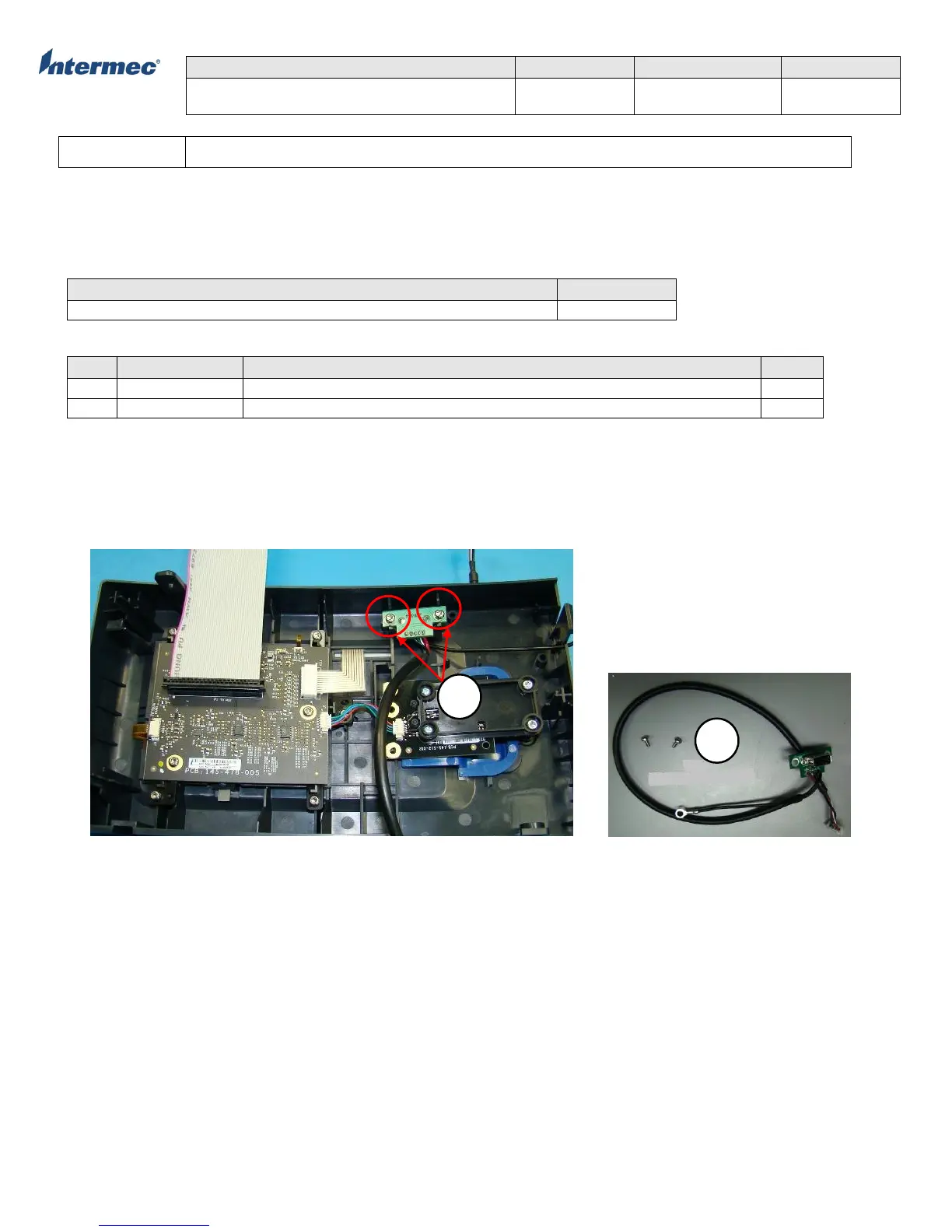
2. Remove the torx screws securing the USB PCBA to the front panel and remove the front panel USB connector. See Figure 1.
3. Disconnect the USB cable from connector P26 on the main logic board (MLB).
4. Reverse the procedure for re-installation.
Figure 1 Front Panel USB Cable Assembly