PM43 Service Work Instructions
Intermec Proprietary Document
User Interface PCB Assembly
This section covers the replacement of user interface PCB assembly. The user interface PCB assembly for full touch
panel is shared between PM43 and PM43c. The user interface PCB assembly for one-button option is not shared
between the two models.
Tools Required
Parts Required
Feed Button PCB Assembly Replacement
1. Remove the front panel to access the LCD display for replacement. See page 11 on how to remove the front panel.
2. Remove the overlay. See page 45 on how to remove the overlay.
3. Lift the connector latching mechanism J1 & J2 on the user interface PCB assembly to release LCD and LCD backlight ribbon
cable. Important to note the direction of the lift. See Figure 2 for reference.
4. Disconnect the keypad, feed button PCB assembly, and touch panel cables.
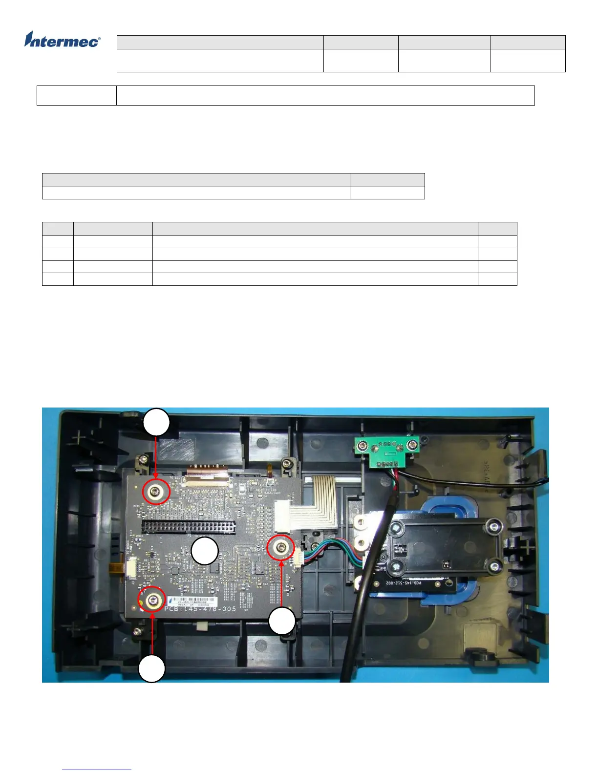
5. Remove the 3 torx screws securing the user interface PCB assembly. See Figure 1 on torx screws location.
6. Reverse the procedure for re-installation.
Figure 1
PCB Assembly, User Interface, Full Touch, PM43&PM43c
PCB Assembly, User Interface, One-Button, PM43
PCB Assembly, User Interace, One-Button, PM43c
Screw, Plastite, M3x6, PH, Torx, T10 (3 lbf.in/3.5kgf.cm)