PM43 Service Work Instructions
Intermec Proprietary Document
LCD Touch Panel Replacement
1. Remove the front panel to access the LCD display for replacement. See page 11 on how to remove the front panel.
2. Remove user interface PCB assembly. See page 43 on how to remove the user interface PCB assembly.
3. Remove the overlay. See page 48 on how to remove the overlay.
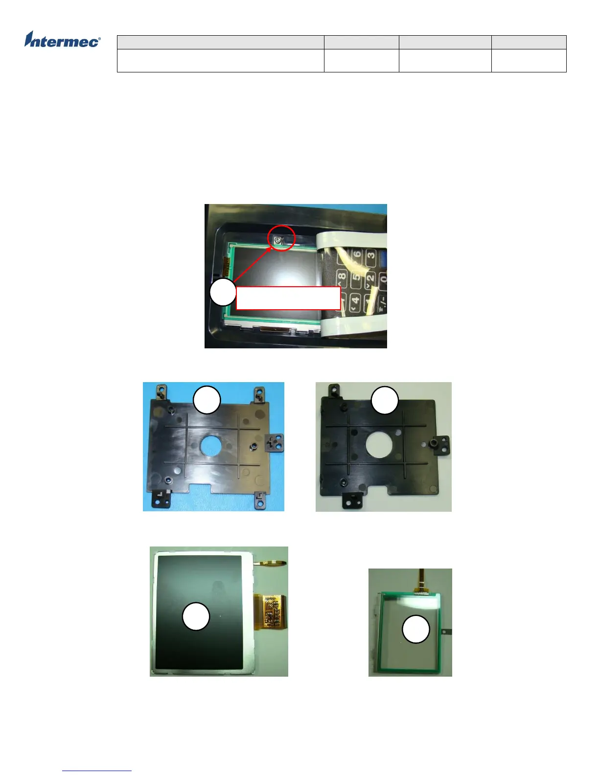
4. Remove the torx screwing the touch panel under the overlay. See Figure 2.
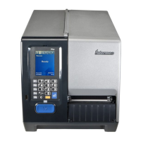
5. Remove the 5 torx screws securing the user interface PCB support bracket. See Figure 1 on torx locations for PM43. PM43c
has 3 torx screws securing the user interace PCB support bracket.
5. Reverse the procedure for re-installation. It is important to note the touch panel ribbon cable routing. See Figure 3 &
Figure4 comparing the correct and incorrect cable routing.
Figure 2
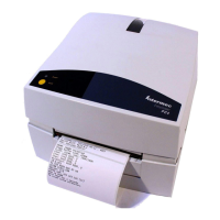
UI PCB Support Bracket, PM43 UI PCB Support Bracket, PM43c
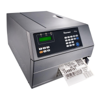
LCD Display Assembly LCD Touch Panel