Interroll MultiControl
Product information
Version 2.3 (01/2017) en-US
Translation of original instruction manual
11
The MultiControl does not provide a protective mechanism against excessive temperature of the
connected drive motor.
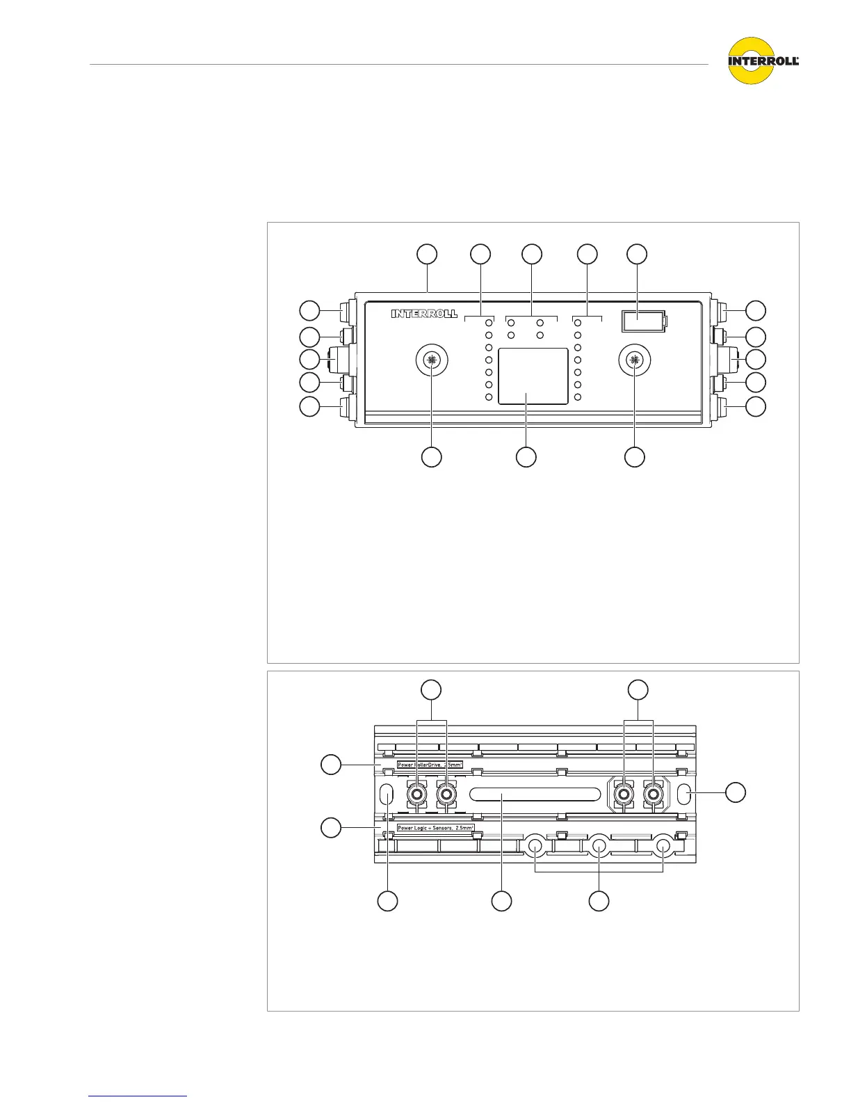
Structure
1 Magnetic sensor 9 Motor connection (RD 4)
2 LEDs for left-hand connections 10 Sensor connection / digital I/O (I/O 4)
3 General LEDs 11 Fastening screw
4 LEDs for right-hand connections 12 Type plate
5 Labeling field 13 Sensor connection / digital I/O (I/O 2)
6 Sensor connection / digital I/O (I/O 3) 14 Motor connection (RD 2)
7 Motor connection (RD 3) 15 Motor connection (RD 1)
8 Bus connection (A/B link) 16 Sensor connection / digital I/O (I/O 1)
1 RollerDrive power supply flat cable guide (L2)
2 Logic and sensor power supply flat cable guide (L1)
3 Screw guides for fastening the MultiControl
4 Holes for fastening the baseplate to the conveyor