Interroll MultiControl
Assembly and installation
20 Version 2.3 (01/2017) en-US
Translation of original instruction manual
4 Connect the line to the voltage source by connecting the brown core at L+ and the blue core
at L-.
If the MultiControl has to be removed after bonding, the flat cable must not be reconnected at
the same point as otherwise a proper contact cannot be ensured. In this case, the MultiControl
has to be repositioned (see "Repeated assembly", page17).
NOTICE
Short circuit from incorrect polarity
If the voltage supply is connected with incorrect polarity, it leads to a short circuit in the line
because of the reverse polarity protection in the MultiControl.
4 Install a suitable protection mechanism so that the MultiControl and the line are not
overloaded.
4 Have an electrician undertake the dimensioning of the protection mechanism.
4 When selecting the line protection, pay particular attention to the maximum short circuit
current of the voltage supply.
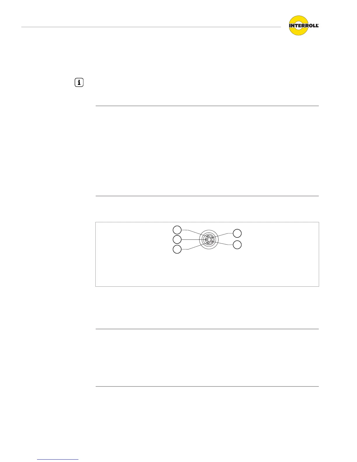
Connecting the RollerDrive
The four connectors 'RD1' to 'RD4' are prepared for the RollerDrive EC310. The RollerDrive
EC310 connection cable is already fitted with a suitable plug.
1 +24 V 4 Fault input
2 Output for direction of rotation 5 Speed output
3 Ground
4 Insert the plug so that the labeling EC310 on the plug points to the rear, i.e. it cannot be
read.
4 Close unused RollerDrive connections with M8 dummy cap to achieve degree of protection
IP54.
NOTICE
Connections are not short circuit-proof
In case of a short circuit, particularly between Pin 1 and Pin 3, the internal fuse in the
MultiControl trips. The internal fuse cannot be replaced.
4 Ensure the correct polarity.