Interroll MultiControl
Assembly and installation
Version 2.3 (01/2017) en-US
Translation of original instruction manual
19
Electrical installation
Connect the power supply
One or two flat cables of type 3G3G-FL with a core cross-section of 2x 2.5mm² are used for
the power supply:
• When using a flat cable, the MultiControl, the RollerDrive, the sensors and the logic are
supplied by the same voltage source.
• If two flat cables are used, the sensors and the logic are supplied with separate voltage
sources. This allows the RollerDrive to be switched off without losing the bus communication.
The two ground potentials (L-) of the voltage supply are connected with each other in the
MultiControl. The two positive contacts (L+) are connected with each other via a diode in the
MultiControl. This ensures that the logic can also be supplied via the RollerDrive line, but not the
RollerDrive via the logic supply.
4 Observe the national regulations for laying the flat cables. DIN EN 60204-1 applies in
Europe.
4 Use only flat cables of type 3G3G-FL with a core cross-section of 2x 2.5mm².
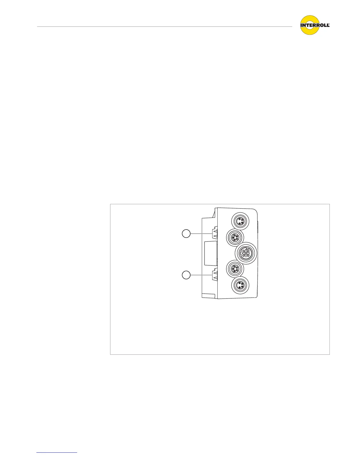
4 Insert the flat cable in the cable duct on the base plate in its correct orientation without
mechanical tension and without torsion. The cable ducts have a form-fit design (see graphic).
As such, the flat cable can only be laid in one direction and polarity cannot be reversed.
1 Cable duct for RollerDrive voltage supply
Pin at top: L+, brown core of line
Pin at bottom: L-, blue core of line
2 Cable duct for logic and sensor system voltage supply
Pin at top: L+, brown core of line
Pin at bottom: L-, blue core of line
4 If only one voltage supply is used, use the top cable duct with the label "Power
RollerDrive" (1). In this case, close the lower cable duct (2) with a stub to achieve protection
rating IP54.
4 If necessary take measures for strain relief or vibration reduction.
4 Close the ends of the flat cables with end caps to achieve protection rating IP54.
4 Install MultiControl on the base frame to establish the correct contact bonding (see "Initial
assembly", page16).