Goodrive350 IP55 High-ingress Protection Series VFD Function parameter list
-230-
Relay RO8
switch-on delay
Relay RO8
switch-off delay
Relay RO9
switch-on delay
Relay RO9
switch-off delay
Relay RO10
switch-on delay
Relay RO10
switch-off delay
Lower limit of
AO2 output
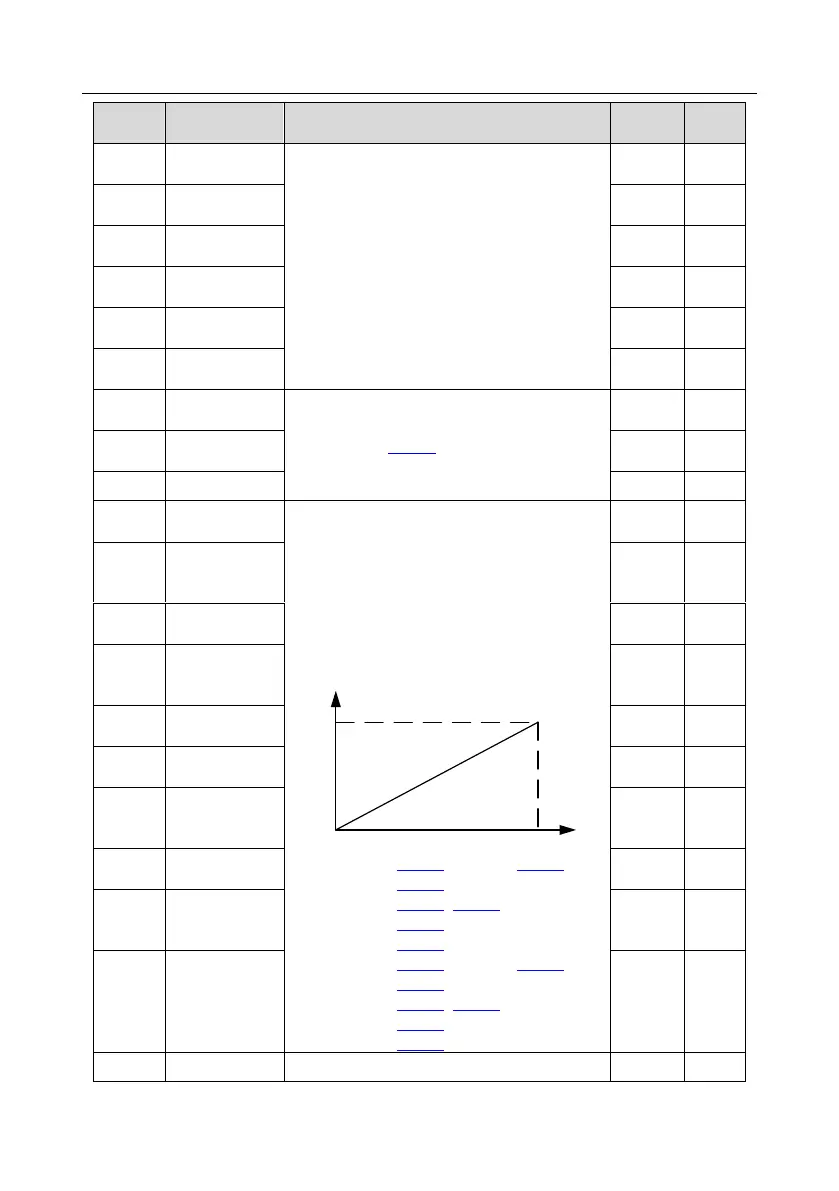
Above function codes define the relation
between output value and analog output. When
the output value exceeds the set max./min.
output range, the upper/low limit of output will be
adopted during calculation.
When analog output is current output, 1mA
corresponds to 0.5V voltage. In different
applications, 100% of output value corresponds
to different analog outputs.
Setting range of P26.38: -300.0%–P26.40
Setting range of P26.39: 0.00V–10.00V
Setting range of P26.40: P26.38–100.0%
Setting range of P26.41: 0.00V–10.00V
Setting range of P26.42: 0.000s–10.000s
Setting range of P26.43: -300.0%–P26.45
Setting range of P26.44: 0.00V–10.00V
Setting range of P26.45: P26.43–300.0%
Setting range of P26.46: 0.00V–10.00V
Setting range of P26.47: 0.000s–10.000s
Corresponding
AO2 output of
lower limit
Upper limit of
AO2 output
Corresponding
AO2 output of
upper limit
Lower limit of
AO3 output
Corresponding
AO3 output of
lower limit
Upper limit of
AO3 output
Corresponding
AO3 output of
upper limit
 Loading...