117
CHAPTER 10. MOWER DECK
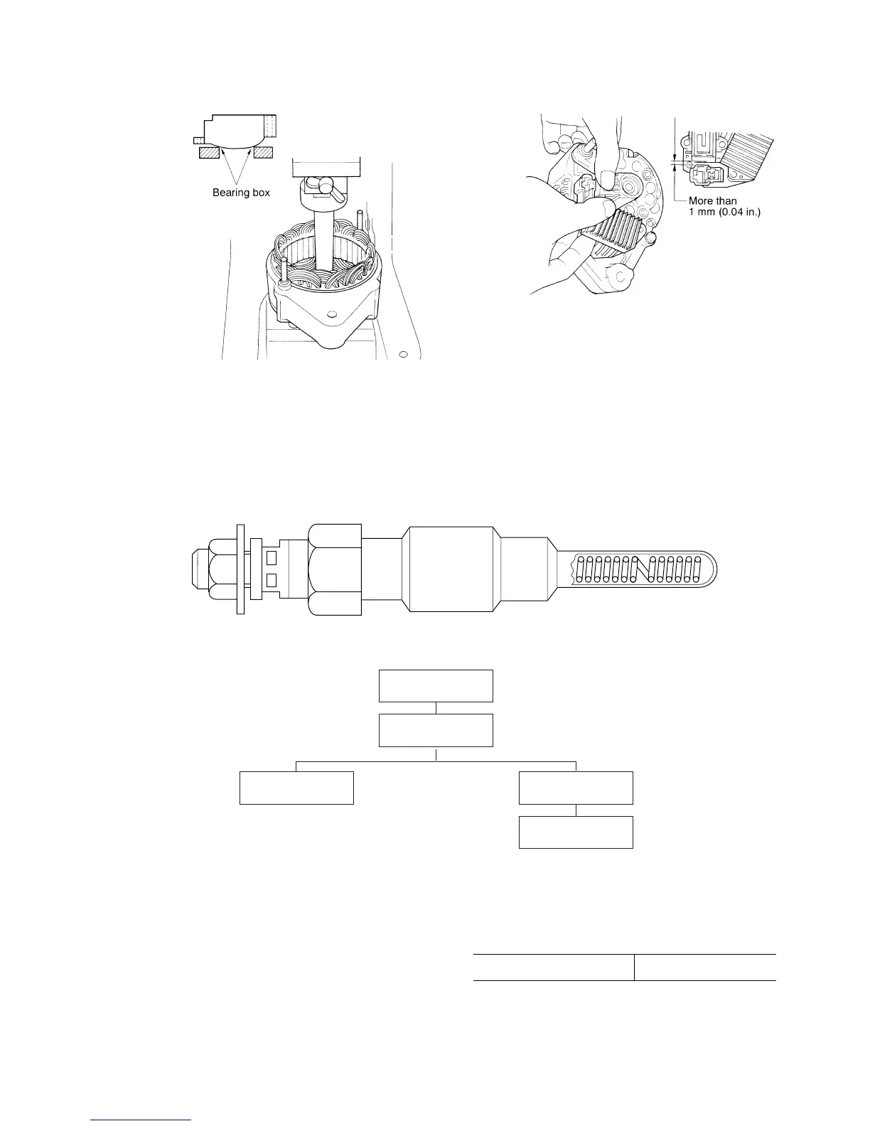
7. GLOW PLUGS
7.1. SECTIONAL VIEW
Fig. 9-62
7.2. REMOVAL, INSPECTION, AND RE-ASSEMBLY
a. Troubleshooting
b. Removal
• Remove the connector by loosening the glow
plug nut installed on the cylinder head.
• Remove the glow plug.
c. Inspection
• Check for continuity across the sheath and center
Fig. 9-60
2) Installation of the brush holder
Install the brush holder sideways along with the
IC regulator.
Fig. 9-61
Note:
- The clearance between the brush holder and the
connector should be 1 mm or more.
- Rubber packing for the brush holder should not
be deformed or pinched.
- As the terminals have screws different in length,
be sure not to confuse them when installing.
electrode. If there is no resistance, it indicates a
short circuit, so replace the glow plug. If the re-
sistance is infinite, it shows that pre-heating coil
is burnt out, so replace the glow plug.
Standard value 2.0 Ω
d. Re-installation
• Install the glow plug.
• Install the nut on the glow plug and connect the
connector.
Improper preheating
Check pre-heating coil.
Replace glow plug.
Check other inner
wiring for short.
Replace glow plug.
 Loading...