32
SERVICE MANUAL FOR SGR19 & SGR17
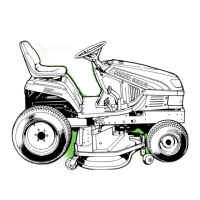
Standard value Usable limit
Clearance 0.01 – 0.05 mm 0.2 mm
Fig. 3-39
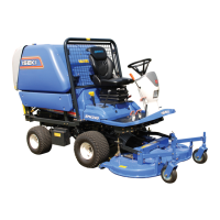
(5) Reassembly of the rocker arm shaft assembly
• Arrange the rocker arms so that the sides where
identification markings were put when disas-
sembled are turned forward. Make sure that the
shaft is placed with the end having an off-set
positioning bolt hole turned forward.
Fig. 3-40
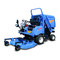
5. INSPECTION OF THE PUSH RODS
• Check both ends of each push rod for wear.
Replace excessively worn rods with new ones.
• Check push rods for bending.
Place a rod on a surface table and measure bend-
ing with thickness gauges.
Usable limit
Push-rod bending 0.3 mm
Fig. 3-41
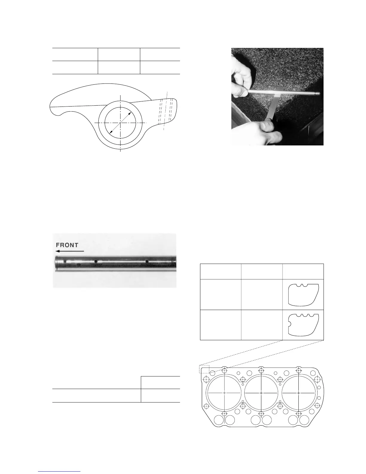
6. INSTALLATION OF THE CYLINDER HEAD
(1) Installation of the cylinder head
• Clean the bottom surface of the cylinder head
and the top surface of the cylinder block.
• Drive in dowels.
• Insert tappets.
• Put a new gasket with its “TOP” mark turned
upward.
• A gasket of different models has a different iden-
tification marking: notches in the left top cor-
ner as shown below.
Engine model
Cylinder bore
(mm)
Identification
notches
E393
E383
Ø74
Ø70
Fig. 3-42
 Loading...