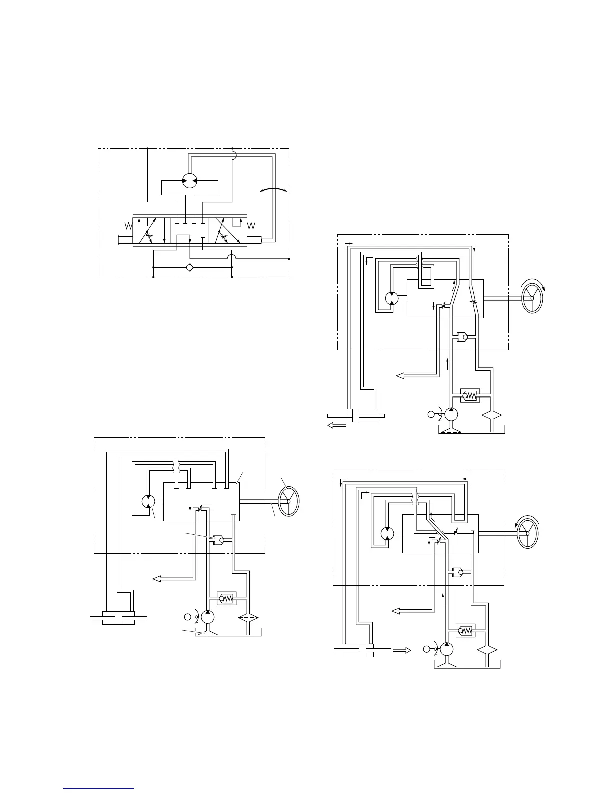
Fig. 7-2
2.1. When the steering wheel is in the neutral
position:
Fig. 7-3 is the functional diagram when the mini-
orbit roll is shifted in the neutral position. As the
diagarm shows all the ports except for port EF
are blocked. All fluid from the pump goes via
port EF to the circuit of another acutator.
Fig. 7-3: when the steering wheel is in neutral
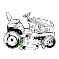
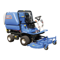
2.2. When the steering wheel is operated:
The working diagrams when the steering wheel
is turned in either direction are shown in Fig. 7-
4 and 5: Fig. 7-4 when the steering wheel is
turned to right; Fig. 7-5 when the wheel is turned
to left. While the steering wheel is being turned,
some fluid from the pump goes to a cylinder port:
port R when turned to right; port L when turned
to left and the other flows to port EF. The steer-
ing system has the priority to other hydraulic
functions, the fluid used in the steering system
returns via port T to the oil reservoir, and the
rest goes to other actuators, which makes
sumultaneous hydraulic operation partially pos-
sible.
Fig. 7-4 (When the steering wheel is turned to right)
Fig. 7-5 (When the steering wheel is turned to left)