35
CHAPTER 3. ENGINE
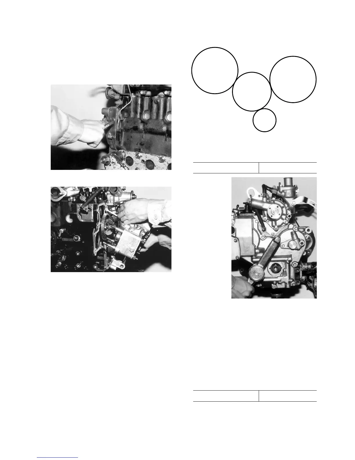
Note:
Note which bolt is to be installed in which place
for later reference and remember to remove the
bolts which also tighten the case from behind.
Fig. 3-51
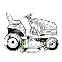
Fig. 3-52
• Discard removed packings and oil seals and use
new ones during re-assembly.
Note:
It is recommended not to disassemble the oil
pump assembly, relief valve, governor, and re-
lated parts which are installed inside the gear
case except when required.
3. RE-INSTALLATION OF THE GEAR
CASE
• Install the idle gear.
• Apply oil to the bore surface of the idle gear and
install taking care to align the timing marks with
those of other gears.
Fig. 3-53
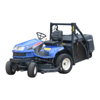
• Install the gear case.
Specified torque 1.4 – 2.4 kgf·m
Fig. 3-54
• Connect the rack of the injection pump and the
control link with a setting spring. After installa-
tion, confirm their smooth working by moving
the rack several times.
• Install the starting spring. Take care not to drop
the spring.
• Install the injection pump cover, using new pack-
ing.
• Install the crankshaft pulley and tighten to the
specified torque.
Specified torque 17.0 – 20.8 kgf·m
• Install the alternator.
• Install the fan belt and cooling fan.