46
SERVICE MANUAL FOR SGR19 & SGR17
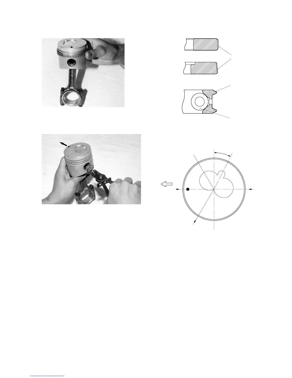
Fig. 3-89
• Install the other snap ring securely in the groove.
Fig. 3-91
• Install the rings with their gaps 120° apart from
each other as shown in the figure.
Fig. 3-90
(2) Installation of piston rings
• Install the rings using a piston ring expander with
their “T” marks turned upwards. But the oil rings
have no markings, so they can be installed with
either side up.
• The gaps of the ring and ring expander of the oil
ring should be set apart 180° from each other.
Note:
As No.1 and No.2 compression rings have dif-
ferent cross sections, take care not to install them
in wrong order.
No. 2
compression
ring
No. 1
compression
ring
Expander
joint
Oil ring
27°
Front
Fig. 3-92
6. INSTALLATION OF CRANKSHAFT
(1) Install the upper bearings, which have oil grooves
or oil holes, in the cylinder block.
Note:
Bearings and bearing fitting surfaces on the cyl-
inder block should be free from any foreign mat-
ter.
The projection of each bearing should be se-
curely seated in its notch in the cylinder block.
FRONT
1st
2nd
Oil
Chrome-plated
Chrome-plated
Coil expanders
 Loading...