99
CHAPTER 9. ELECTRICAL ACCESSORIES
3.4. REINSTALLATION AND ADJUSTMENT
Reassmebly of the steering gear box
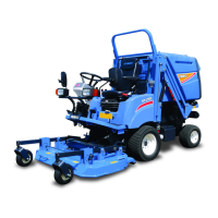
– Install the control flange (for gear backlash ad-
justment) offset downwards as illustrated. Install
two RBB’s and retain them with the snap ring.
The outside RBB has a seal on one side only.
Install it with the seal turned outward.
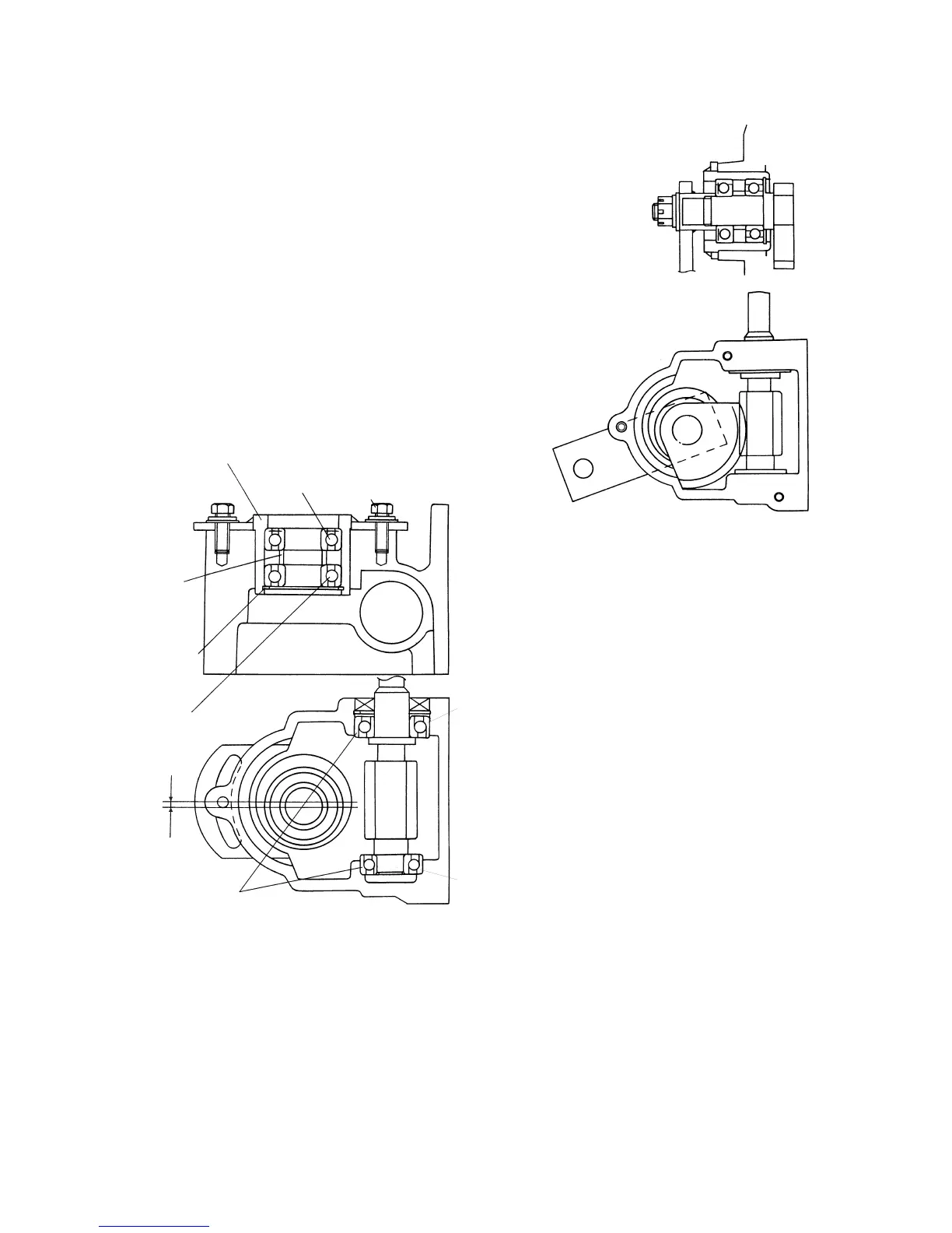
– As for the angular roller bearings for the steer-
ing shaft, bearing (A) should be installed so that
it can support downward thrust. Insert the steer-
ing shaft. Install bearing (B) on the steering shaft.
Push the bearing to the case
Control flange
RBB
(one side sealed)
Bolt
Collar
(21×25×08)
Snap ring
RBB
Angular roller bearings
Off-set
B
A
Fig. 8-6
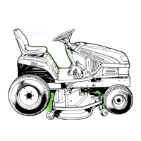
– Install the drag arm on the helical gear shaft by
aligning by aligning mutual splines so that the
drag arm’s centre axis becomes aligned with the
axis of the cotter pin hole in the shaft as illus-
trated.
Fig. 8-7
Gear backlash
Loosen the control flange tightening bolts and
turn the flange clockwise to increase and
counterclockwise to decrease backlash.