56
SERVICE MANUAL FOR SGR19 & SGR17
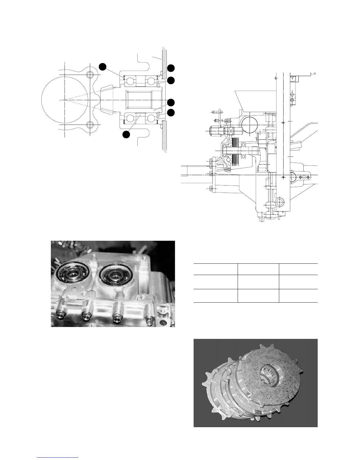
(1) Input gear (12T) (4) Washer (31×42×1)
(2) Collar (31×38×11) A, B: Shimming points
(3) Snap-ring
Fig. 4-13
(6) Install the left wheel assembly and HST unit.
• Apply grease and take care not to damage the
O-ring.
Fig. 4-14
5. BRAKE SYSTEM
5.1. CONSTRUCTION
Fig. 4-15
5.2. INSPECTION
(1) Check the brake discs and seperator plates for
wear, flaws, deformation, etc. Defective parts
should be replaced with new ones.
Standard value Usable limit
Brake disc 3.5 mm 2.9 mm
Separator plate 1.52 mm 1.46 mm
(2) Check the actuator ball and ball way for abnor-
mal wear, defective parts should be replaced with
new ones.
Fig. 4-16
1
2
3
4
B
A
Plate