55
CHAPTER 4. TRANSMISSION & RELATED PARTS
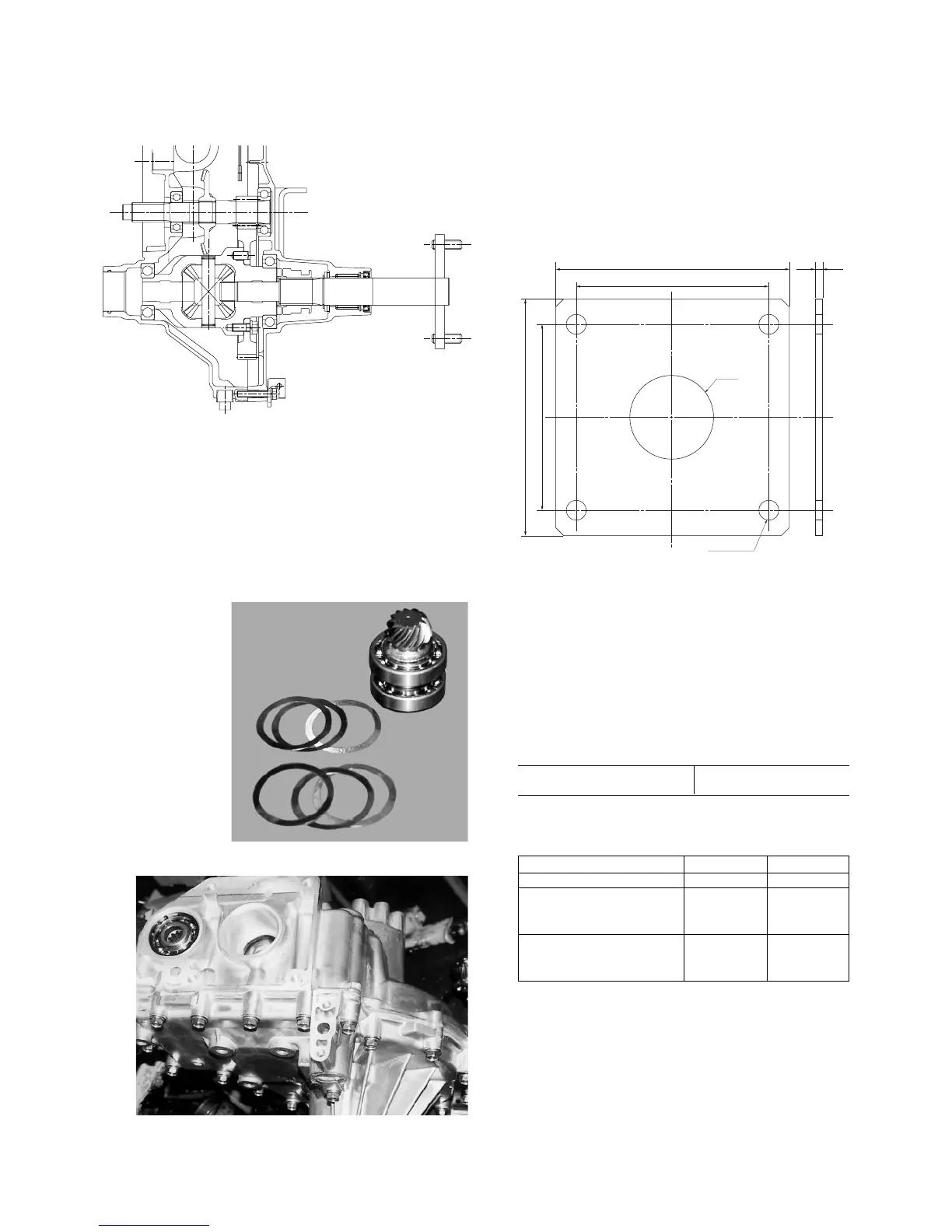
Fig. 4-9
(5) Adjustment of drive pinion backlash
Adjust the backlash between the drive pinion and
the ring gear by shimming.
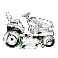
Fig. 4-10
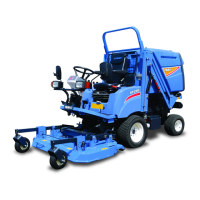
Fig. 4-11
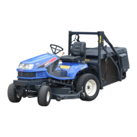
a. Measuring tools
• Holder of drive pinion set
• Dial guage setting tool
Fig. 4-12
b. If the measurement is deviates from the speci-
fied range at the point 150 mm apart from the
drive pinion center, correct by shimming at A
and B.
Backlash of drive pinion
Standard value 0.1 – 0.3 mm
Required number of shims
Side A Side B
Standard 3 3
To extend 4 2
51
60
To close 2 4
15
06