28
SERVICE MANUAL FOR SGR19 & SGR17
2. DISASSEMBLY
(1) Removal of the inlet manifold.
(2) Removal of the exhaust manifold.
(3) Removal of the thermostat housing.
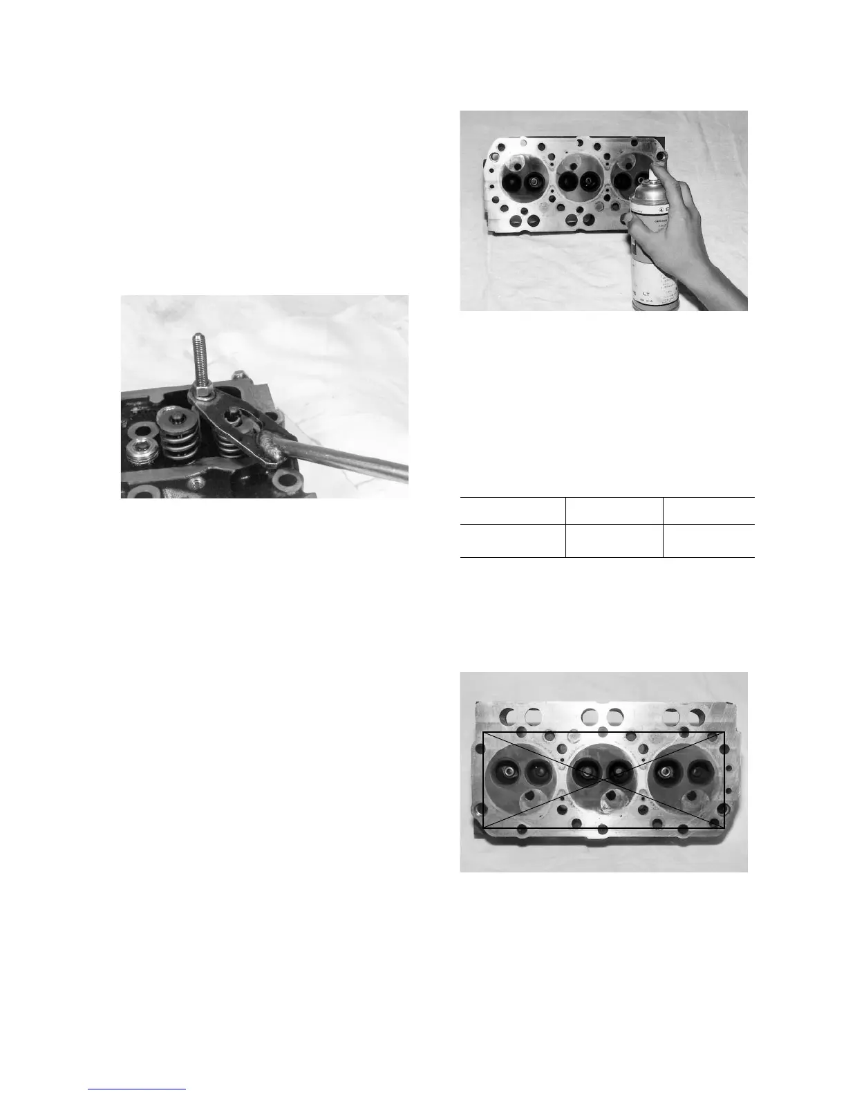
(4) Removal of the valves.
Fig. 3-24
• Compress the valve spring along with the spring
seat with a spring compressor, and remove the
cotter spring seat retainer.
Note:
Removed valve and related parts should be put
aside in order of valve numbers.
(5) Removal of the valve oil seals.
Note:
Discard removed valve oil seals.
3. INSPECTION
(1) Inspection of the cylinder head for cracks.
• Remove carbon deposit from the bottom surface
of the cylinder head.
• Inspect the bottom surface and inlet and exhaust
ports using “COLOR CHECK.”
Fig. 3-25
(2) Inspection of the cylinder head for distortion
• Measure the flatness of the bottom surface of
the cylinder head by putting a straight rule di-
agonally across the four corners on the bottom
face and check for clearance with thickness
gauges.
Standard value Usable limit
Distortion 0.075 mm 0.15 mm
• When the distortion exceeds the usable limit,
correct on a surface grinder.
• As the ground-down limit is 0.4 mm (0.016 in.),
replace a cylinder head assembly which required
more than the ground-down limit to correct.
Fig. 3-26
(3) Inspection of the clearance between the valve
guide and valve stem.
• Check the valve for play with a dial indicator. If
the play exceeds 0.15 mm for the inlet valve and
0.2 mm for the exhaust valve, replace both the
 Loading...