19
CHAPTER 2. DISASSEMBLY OF MAJOR COMPONENTS
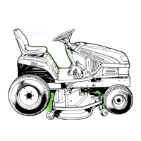
(7) Remove the delivery pipe to the solenoid valve.
Fig. 2-33
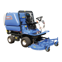
(8) Remove the HST tension spring and the assem-
bly of the HST controlling rods.
Fig. 2-34
–
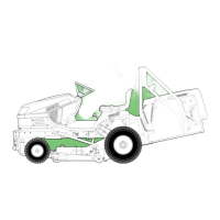
Hold the transmission case with jacks or other ap-
propriate supports and hang the chassis with a hoist.
Fig. 2-36
– Remove the transmission tightening bolts.
Fig. 2-37
(10) Remove the HST unit.
– Remove the suction pipe and filter.
– Remove the HST unit tightening bolts. Then the
unit can be removed from the transmission case.
REINSTALLATION
Reinstall in reverse order of removal, taking the
following precautions.
Reinstall in reverse order of removal, taking the
following precautions.
– Be sure to install O-rings for all hydraulic pipes.
– Each bolt and nut should be tightened to respec-
tive specified torque values referring to the tight-
ening torque table.
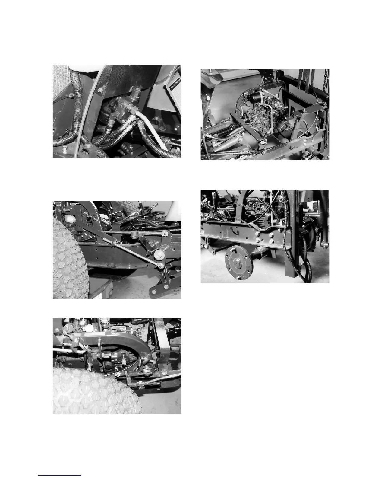
Fig. 2-35
(9) Remove the transmission case along with the
HST unit from the chassis.
 Loading...