33
CHAPTER 3. ENGINE
(4) Installation of the leak hoses.
Fig. 3-45
(5) Installation of the push rods
Fig. 3-46
(6) Installation of the rocker arm assembly
• Loosen all rocker arm adjusting screws.
• Install the rocker arm assembly and tighten it to
the specified torque.
Specified torque 1.4 – 2.4 kgf·m
Fig. 3-47
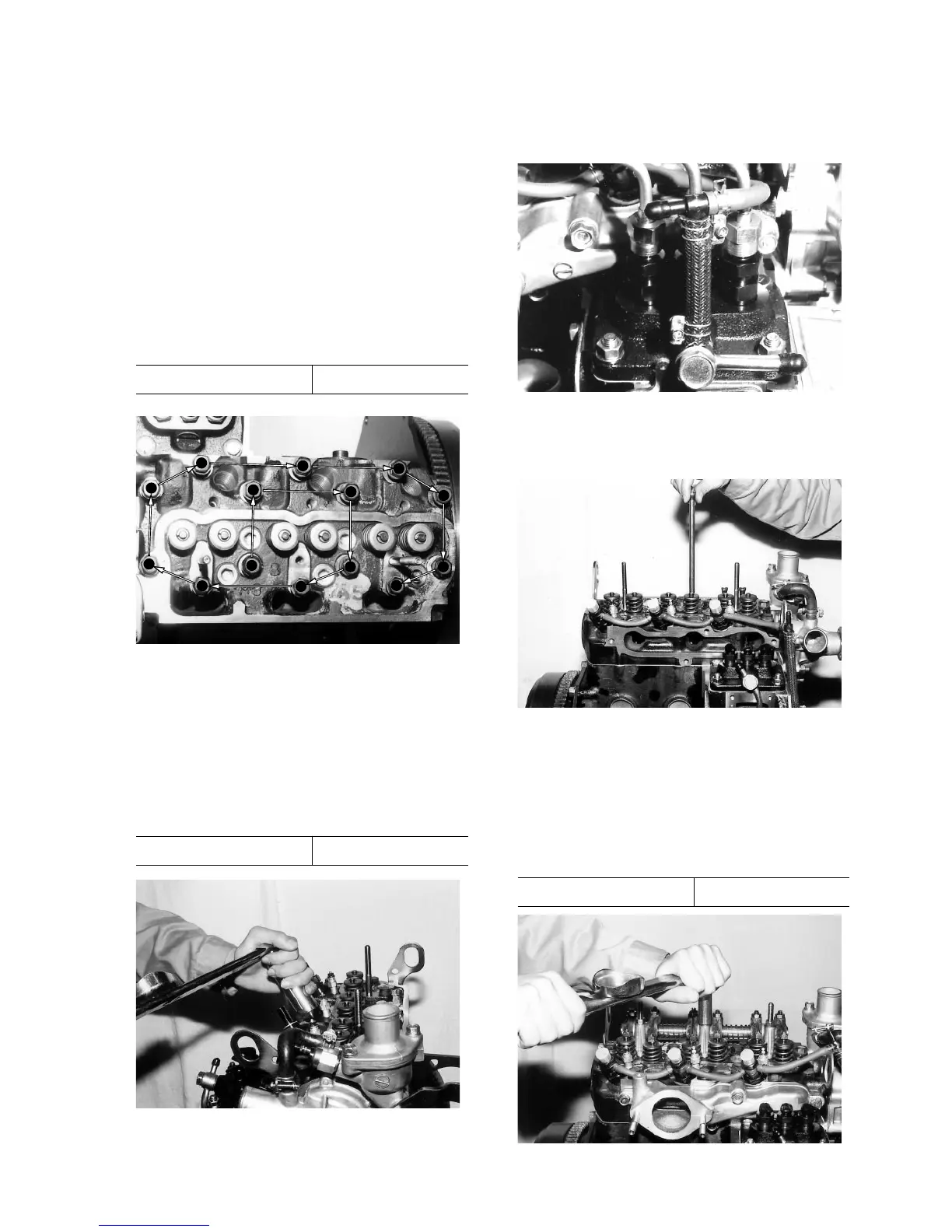
• Place the cylinder head softly on the cylinder
block.
• Apply engine oil to the threads of the cylinder
head bolts.
• Tighten the cylinder head bolts in the sequence
as shown in Fig. IV-31 to the specified torque.
• Be sure to tighten the bolts step by step: first to
2 kgf·m (14 ft·lbs), second to 4 kgf·m (29 ft·lbs),
and then lastly to the following torques.
Specified torque 5.5 – 6.0 kgf·m
1
2
3
4
5
6
7
8
9
10
11
12
13
14
Fig. 3-43
(2) Installation of the glow plugs
(3) Installation of the injection nozzles
• Be sure to use new packings and tighten the noz-
zles to the specified torque.
Specified torque 4.0 – 5.5 kgf·m
Fig. 3-44
 Loading...