121
CHAPTER 10. MOWER DECK
3.1.2. BACKLASH ADJUSTMENT
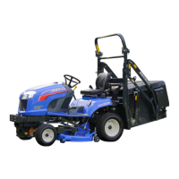
(1) Prepare the jig as show in the drawing to measure the backlash at R25 mm of the output shaft.
Adjusting shims (0.1, 0.2 mm)
Adjusting shims (0.1, 0.2 mm)
Lock this shaft
for backlash
measurement.
R25 mm
Fig. 10-3
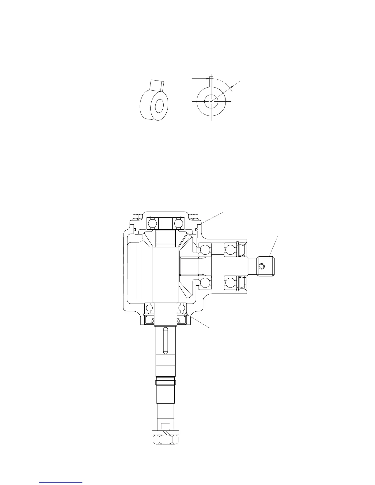
(2) Reassemble the gear box assembly and place it sideways and lock the input shaft in order to prevent it
from turning. (The input shaft has a splined end.)
(3) Install the jig on the output shaft end.
(4) Measure the backlash at 25-mm radius circumference and correct it if required by shimming.
Standard value: 0.3 – 0.5 mm (including spline play between respective bevel gear and shaft)
Fig. 10-4
 Loading...