63
CHAPTER 5. HYDROSTATIC TRANSMISSION
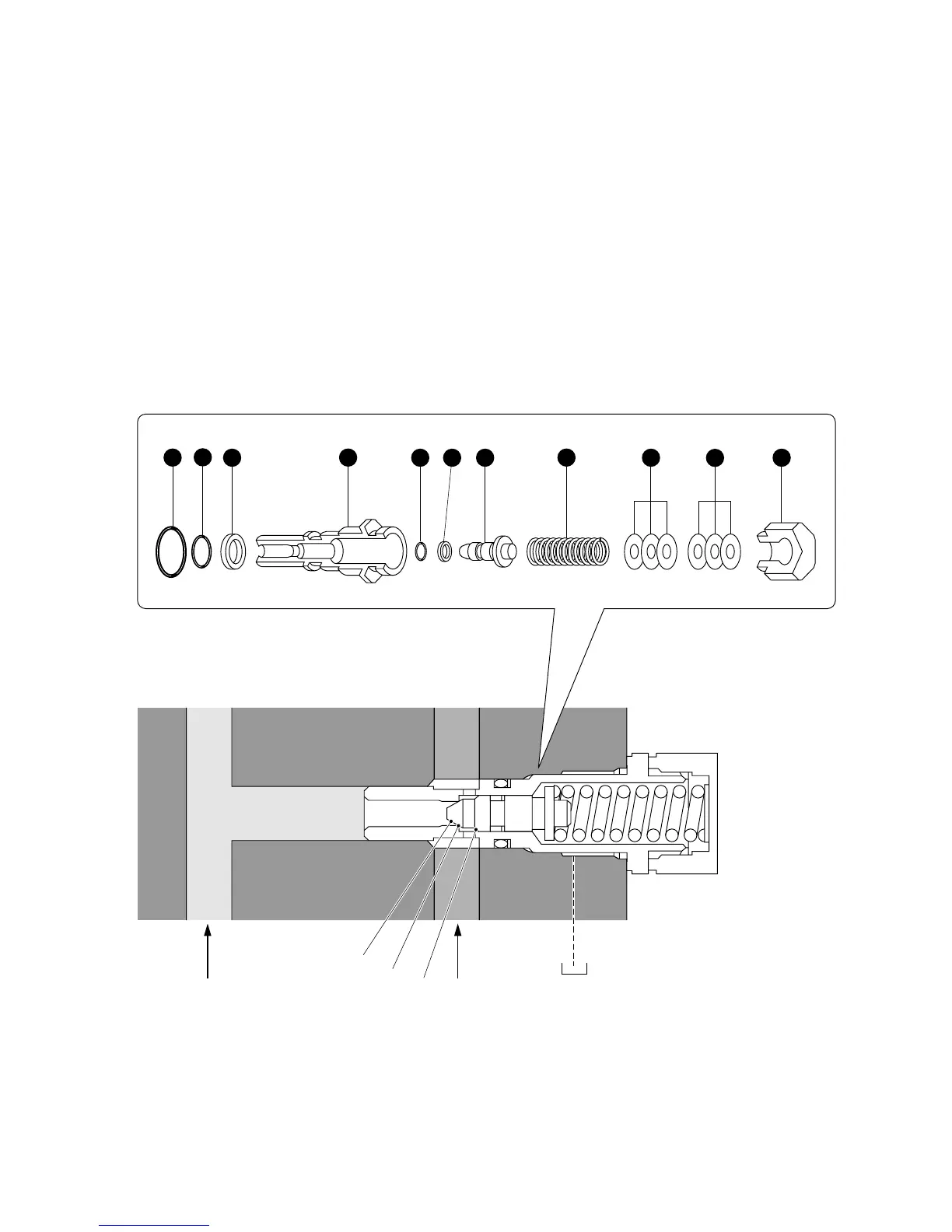
HIGH PRESSURE RELIEF VALVE
A direct type both-direction relief valve is installed across the main passages A and B. The valve con-
trols the pressure in both passages.
When the pressure in the passage A is higher, surface “a” of the poppet receives pressure which pushes
the poppet overcoming the force of the spring and opens the valve: to the left as shown in the figure.
When the valve (part c) opens, the fluid in the passage A flows to the passage B.
When the pressure in the passage B is higher, surface “b” of the poppet receives pressure which pushes
the poppet overcoming the force of the spring and opens the valve: to the right as shown in the figure.
When the valve (part c) opens, the fluid in the passage B flows to the passage A.
AB
a
b
c
(1) Body
(2) Poppet
(3) Nut
(4) Shim A
(5) Shim B
(6) O-ring
(7) O-ring
(8) O-ring
(9) Backup ring
(10) Backup ring
(11) Spring
1
2 34
5
6
7
89 10
11
• 1 mm increase in shimming thickness of shims (4) and (5) increases 40 to 50 kgf in spring force.
Fig. 5-7
 Loading...