Section 3 Installation
30
Adjusting
➀
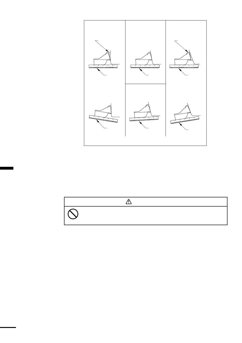
Using a straight edge, sight the underside of the sensor relative to the
underside of the hull. The stern of the sensor should be 1/16-1/8" (1-3mm)
below the bow of the sensor or parallel to the bottom of the hull (see Figure
3-7).
➁
To adjust the sensor’s angle relative to the hull, use the tapered plastic shim
provided. If the bracket has been temporarily fastened to the transom,
remove it. Key the shim in place on the back of the bracket.
2°-10° transom angle (stepped transom and jet boats) - Position the shim
with the tapered end down.
19°-22° transom angle (small aluminum and fiberglass boats) - Position the
shim with the tapered end up.
➂ If the bracket has been temporarily fastened to the transom, remove it. Apply
a marine sealant to the threads of the two #10 x 1-1/4" self-tapping screws to
prevent water seeping into the transom. Screw the bracket to the hull. Do
not tighten the screws completely at this time.
➃
Repeat step 1 to ensure that the angle of the sensor is correct.
11
°
transom angle
12–18
°
transom angle
Sensor angle adjustment on transom
19
°
–22
°
transom angle2
°
–10
°
transom angle
parallel
slight
angle
angle
reversed
angle
too steep
parallel
parallel
shim with
taper down
shim with
taper down
YES
YES
YES YES
NONO
NO SHIM
NO SHIM
Do not position the bow of the sensor lower than
the stern because aeration will occur.
CAUTION
Figure 3-7