Section 3 Installation
39
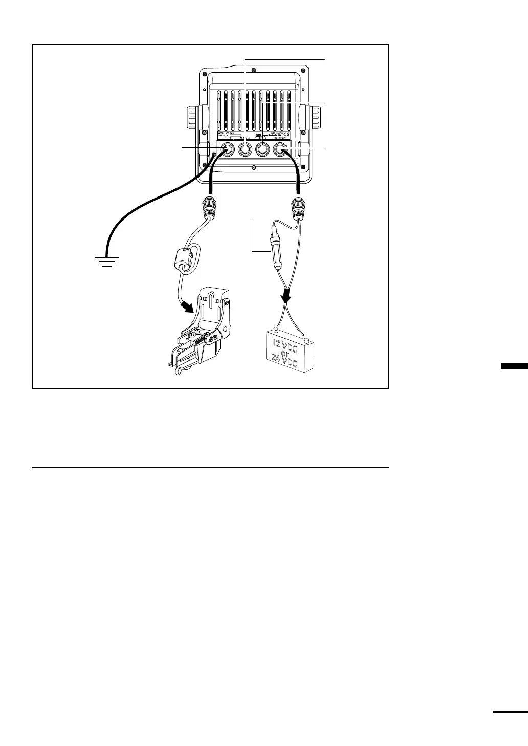
T/D
connector to
transducer
Ship's Ground
System
12/24 VDC
(11-32 VDC)
connector to
battery
Connector to
NMEA 0183
Input/Output
Connector to
GPS/DGPS
Sensor
3 amp fuse
RED
+
BLACK
−
The unit is internally protected
from accidental reverse polarity.
Reversing the power leads will
not damage the unit, it will
simply not turn on.
Figure 3-14
Grounding the Display Unit
One very important requirement in installation of shipboard electronics is to
obtain the cleanest, noise-free environment possible so each piece of electronic
equipment can work to its best performance levels. This requirement is
accomplished by assuring a proper connection from each equipment to the ship’s
RF ground system. The ground provides a drain for shipboard noise transmission
and pickup.
A separate ground wire of # 10 or # 12 AWG (# 10 recommended) should be
connected from the ground terminal on the rear of the unit to the nearest
connection point of the ship’s ground system.
Normally, on a steel hull boat, a good clean connection to the hull provides a
sufficient ground. On a fiberglass or wood hull, connection to a ground plate or
to the engine block and other bonded groundwork should be acceptable.