Section 3 Installation
41
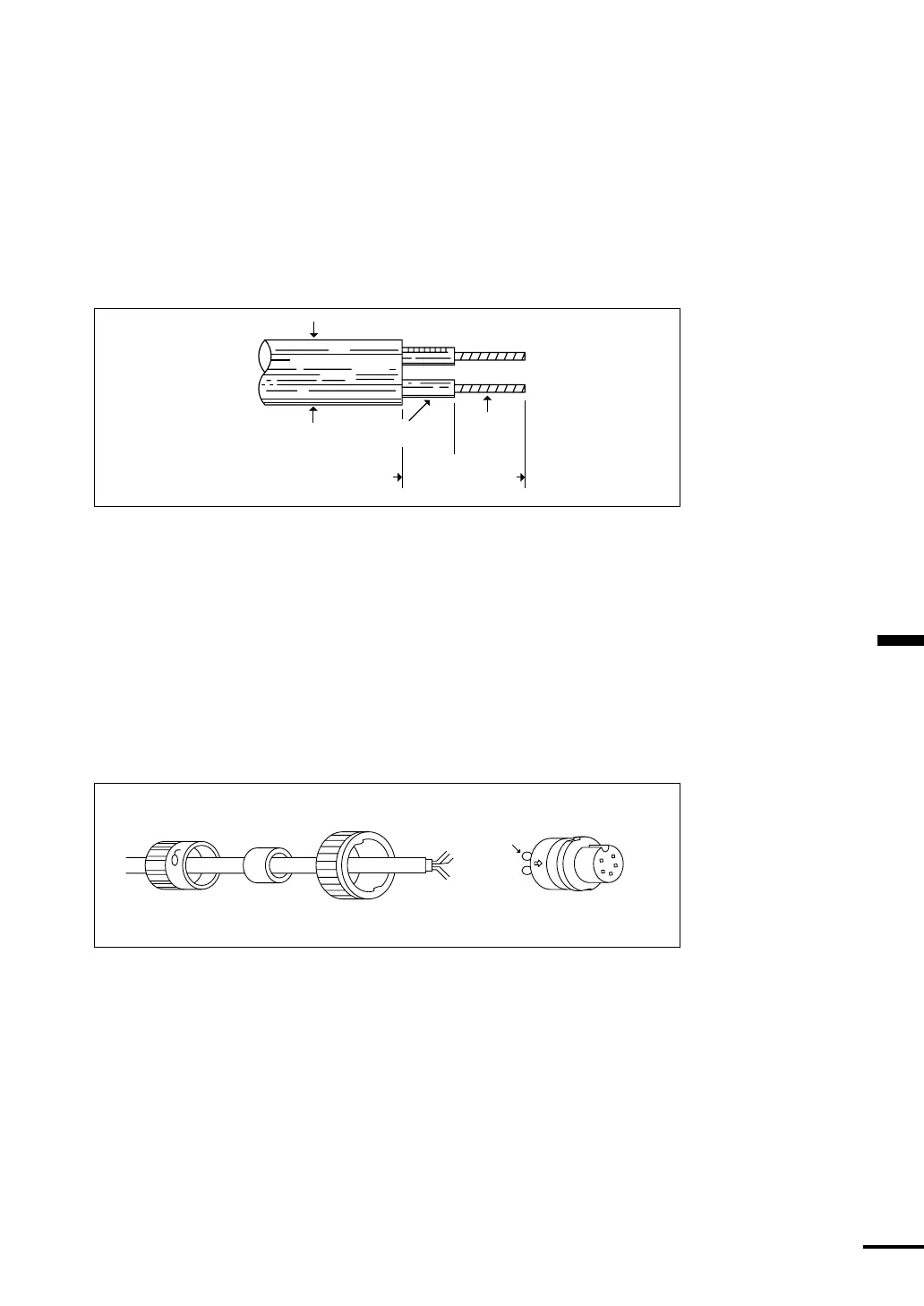
The procedure to assemble the connector is as follows. Please refer to Figure
3-17.
①
Feed the end of the cable through the backshell, rubber grommet and cou-
pling ring in the order and position drawn.
②
Strip the cable as shown in Figure 3-16. Begin soldering the conductors to
the connector pins, as shown in the appropriate diagram for the NMEA
connectors. Verify that each connector is firmly soldered and that no stray
wires are shorting adjacent pins.
Figure 3-16
➂
Slide the coupling ring over the body of the connector and beyond the
locking projections on each side, it may be necessary to rotate the ring
slightly for it to pass by the locking tabs.
➃
Push the rubber grommet forward as far as possible to seat it snugly against
the connector body.
➄
Push the backshell all the way forward. It must first compress the rubber
grommet, then be twisted over the (2) locking posts on the connector body.
This is a tight connection. For leverage it may be helpful to first insert and
lock the connector into its mating plug on the FF50 back panel.
Figure 3-17
GROMMET
PIN
CONTACTS
BACKSHELL COUPLING RING CONNECTOR BODY
3/16"
5/16"
Diameter 0.25"~0.27"
1/2"MAX