Chapter 6 OPTION AND OTHER FUNCTIONS
1
1
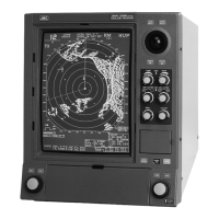
NMEA signal line connector wiring table
GPS
Name Pin No. Signal I/O Color
GPS 1 +12V Out Red
2 GND
㸫
Black
3 GPS
RXD㸫
White
4 RXD+ Green
5 TXD+ Yellow
6
TXD㸫
Brown
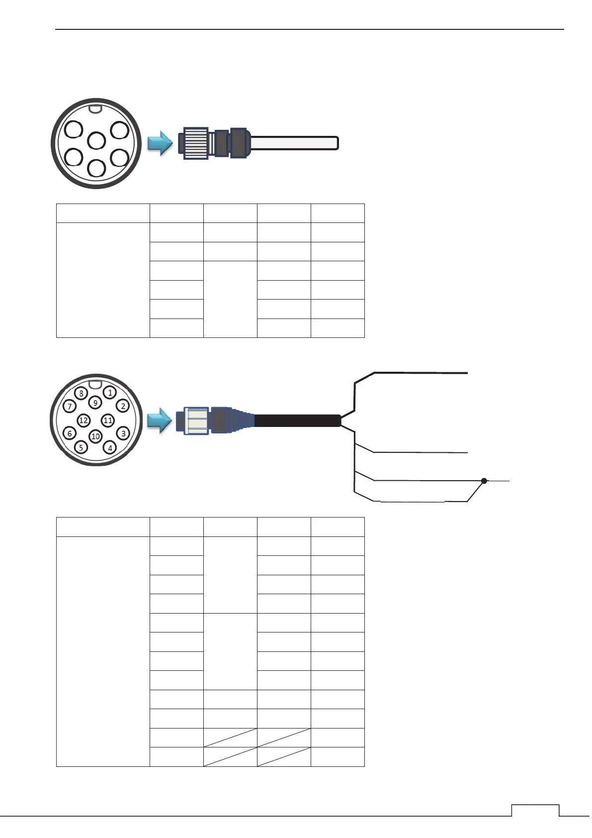
NMEA0183
Name Pin No. Signal I/O Color
NMEA0183 1 NMEA1 RX+(A) Brown
2
RX㸫(B)
Red
3 TX+(A) Orange
4
TX㸫(B)
Yellow
5 NMEA2 RX+(A) Green
6
RX㸫(B)
Blue
7 TX+(A) Purple
8
TX㸫(B)
Gray
9 GND
㸫
White
10 Shield
㸫
Black
11 Pink
12 Sky Blue
1
2
6
3
5
4
[Pink] Unused
[Black]
[Sky Blue]
Connect [Black]
and [Sky Blue]
cables and use
them as shield
wires.
Use the Brown, Red, Orange, Yellow,
Green, Blue, Purple, Gray and White
[Shield]
 Loading...