Chapter 1 INSTALLATION
12
1.3 INSTALLATION OF THE SCANNER UNIT
1.3.1 SELECTING THE INSTALLATION POSITION
PHYSICAL SELECTION CRITERIA
z Install the scanner at the center of the mast on the keel line.
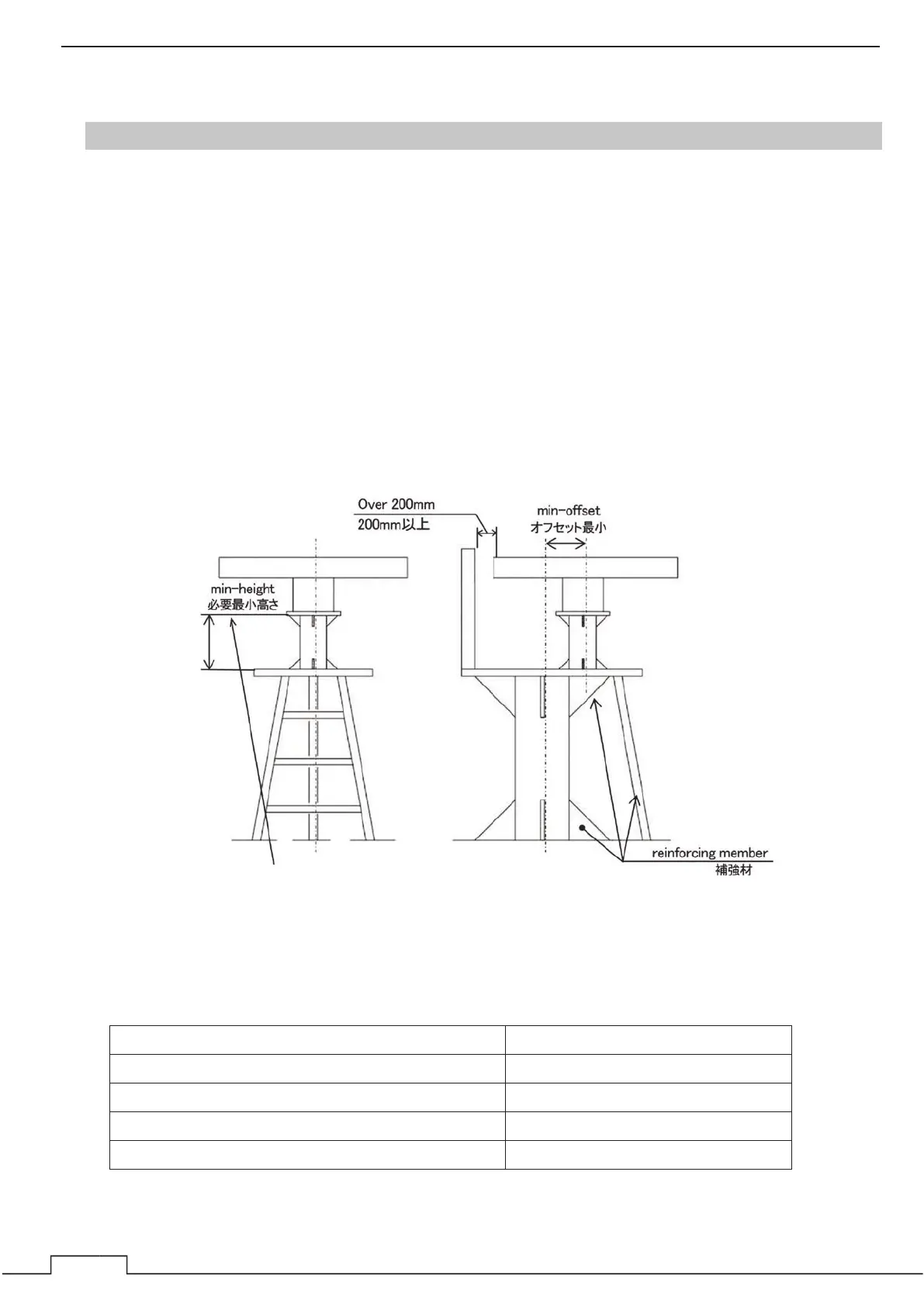
z If the scanner cannot be installed at the above position for some reason, the amount of
deviation must be minimized. And, reinforce the mount base and the platform and take
precautions to protect the scanner from vibration and impact at the installation position.
z To avoid the radiating section coming in contact with other installed objects while it is rotating,
ensure that there is at least 200 millimeters from the swing circle (turning radius) to other
installed objects (Fig. 1-3-1-1). The swing circle of the JMA-3400 radar's scanner is as shown in
Table 1-3-1-2.
z Please note that not affected by the smoke from the chimney.
z Avoid having a rope or signal flag from winding around the radiating section thereby preventing
it from rotating.
z Please secure maintenance spaces (a platform, a safety link, a handrail, a step, etc.).
Fig. 1-3-1-1
Table1-3-1-2
Scanner model (length) Swing circle
NKE-2043 620 mm (radome)
NKE-2063A/AHS (3.9 feet) 1,220 mm
NKE-2103-4/4HS (4 feet) 1,320 mm
NKE-2103-6/6HS (6 feet) 1,910 mm
Set up a scaffolding for maintenance if the minimum height
shown above is 1 m or more.
 Loading...