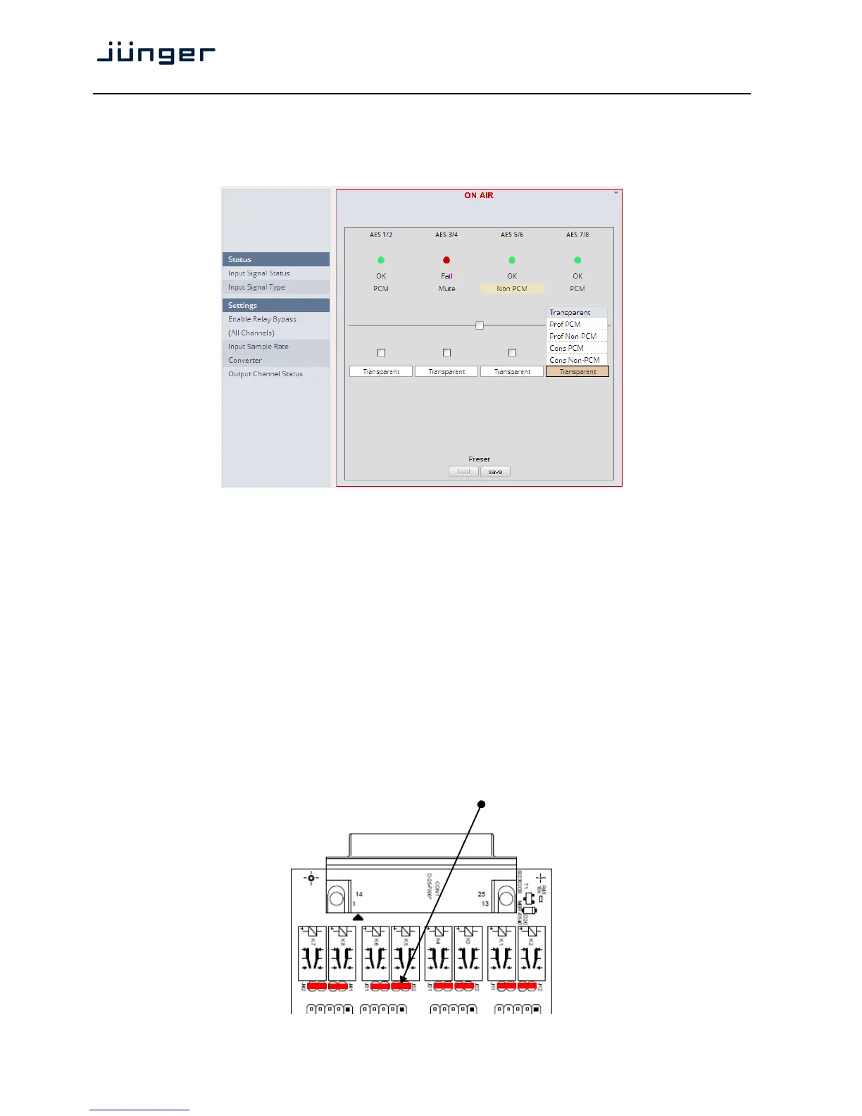
Set up GUI – INTERFACES – AES Interface – Status / Setup
An additional AES3 interface can be installed in the Interface slot.
It provides 4 additional AES3 inputs and outputs on a 25pin D-Sub connector:
Status
Input Signal Status green [OK] / red [Fail]
Input Signal Type [Mute / PCM / Non PCM]}
Settings
Enable Relay Bypass [ON / OFF]
(All Channels) Power fail bypass relay that may be activated from the GUI
Input Sample Rate [ON / OFF]
Converter
Output Channel Status [Transparent / Prof PCM / Prof Non-PCM / Cons PCM /
Cons Non-PCM]
Controls the channel status for the AES output. It provides a set of
useful channel status information (e.g. to prevent non audio signals
to be fed to speakers).
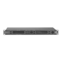
Important note! The AES relay bypass circuit of the I/Os is activated on the option board. It is possible to
deactivate it if necessary. You must open the cover plate from the D*AP4 unit and locate the jumper
shown in the schematic below. You must remove the jumpers to de-activate the AES I/O relay
power fail circuit.