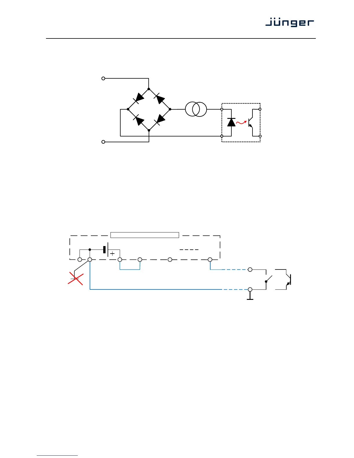
Technical Data – GPI wiring
The device offers a unique circuitry to save GPI setups from hum and noise influence in complex
installations. Here the principle circuit of one of the 8 GPI inputs:
At the GPI input is a bridge rectifier I.e. you do not need to care about the polarity of the input voltage. A
constant current source in line with the optical coupler limits the current.
You must simply provide a voltage in the range from 5 V to 30 V to activate a GPI.
If you have open collector outputs or simple relay closures as the driving GPOs (this technique is commonly
known as "low active" and will be found in most legacy equipment),
you must wire up an auxiliary voltage supply.
The device provides such auxiliary power supply. It offers a balanced 5 V source that you can imaging
as a battery.
Here an example how to wire up GPI #4:
We strongly recommend to spent a wire for ground connection instead of using the chassis common grounds
of an installation.
GPI
common
GPI_x
5 V balanced
1324 25
1
GPI 1, 2, 3, 4
common
GPI 1
2
GPI 4
5
GPO
relay or open collector
25 pin GPI/O connector