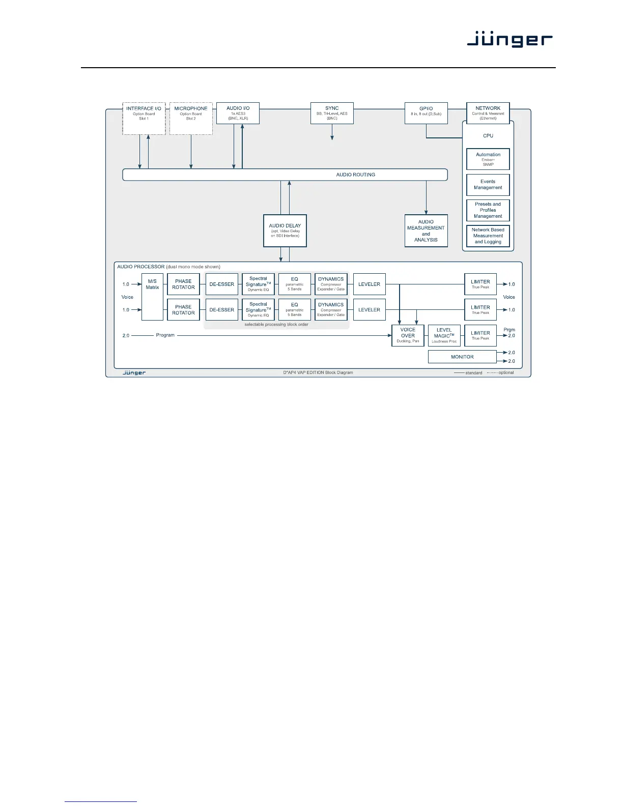
Block Diagram
The above schematic shows the principal blocks of the D*AP4.
The core of the unit is the audio processor with 4 inputs and 4 outputs.
An AES I/O on the motherboard is provided for digital line operation. The respective connectors have relay
bypass for power fail operation. The bypass ciruit may be disabled by an internal jumper. For the 2 channel
version only one AES I/O is fitted.
An interface slot is provided to carry optional 3G / HD / SD-SDI, AES I/O, MADI, DANTE or even analog
expansion modules. It allows for extremely flexible interfacing of the D*AP4 in TV or radio installations.
The sync. circuit can deal with all formats to integrate the D*AP4 into digital facilities with a sample rate from
44.1 or 48kHz. Other devices may be synchronized by the word clock output of the D*AP4.
The D*AP4 has 8 balanced GPIs and 8 relay closure GPO contacts. This enables the user to simply recall
presets or call events, change device configurations and report general status information.