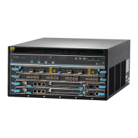
Figure 1: Front Panel of an EX2200 Switch with 48 Gigabit Ethernet Ports
0
1
2
3
4
5
6
7
8
9
10
11
12
13
14
15
16
17
18
19
20
21
22
23
24
25
26
27
28
29
30
31
32
33
34
35
36
37
38
39
40
41
42
43
44
45
0 1 2
SYS
ALM
SPD
DX
EN
POE
3
46
47
Network
ports
Port status mode LEDs
Mode
button
SFP
uplink
ports
Chassis
status
LEDs
g027000
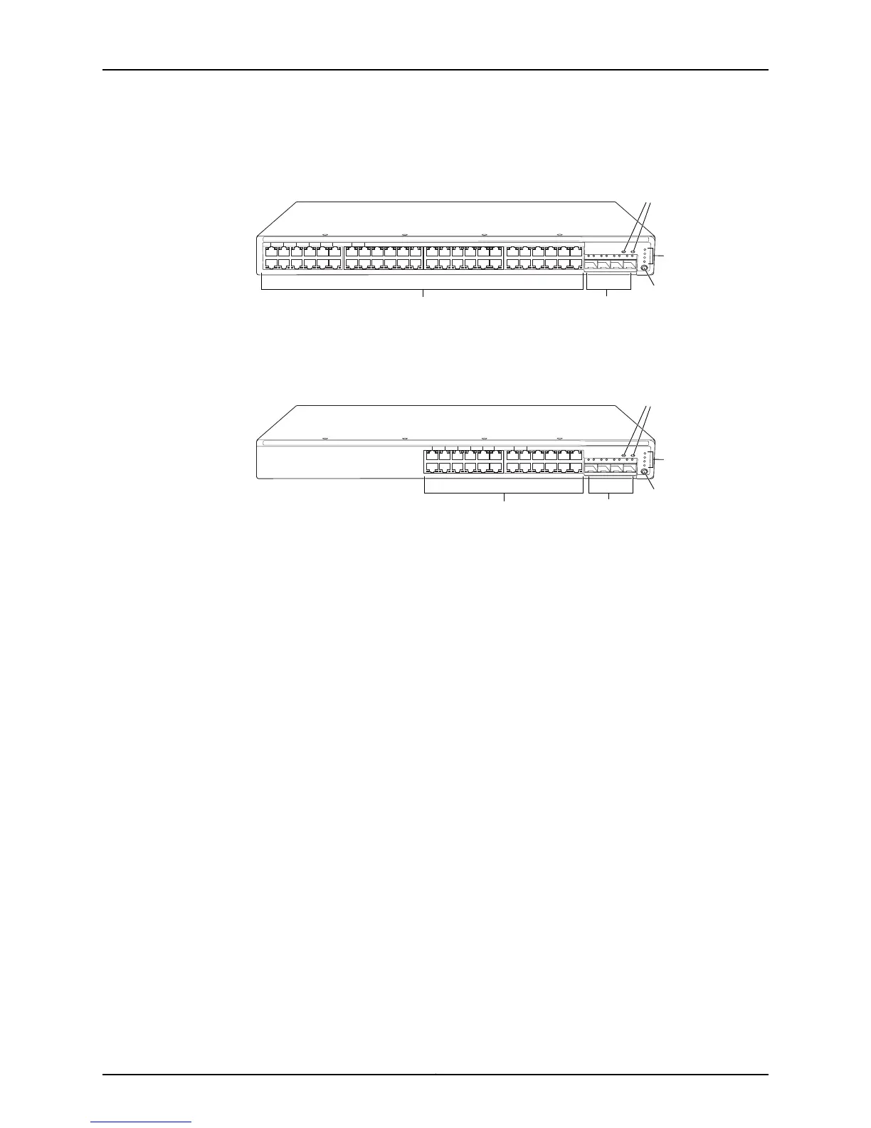
Figure 2: Front Panel of an EX2200 Switch with 24 Gigabit Ethernet Ports
0
1
2
3
4
5
6
7
8
9
10
11
12
13
14
15
16
17
18
19
20
21
22
23
0 1 2
SYS
ALM
SPD
DX
EN
POE
3
Network
ports
Chassis
status
LEDs
g027002
SFP
uplink
ports
Port status mode LEDs
Mode
button
The front panel of an EX2200-C switch consists of the following components:
•
Network ports—depending on the switch model, either of:
•
12 10/100/1000BASE-T Ethernet ports, (non-PoE) in EX2200-C-12T
•
12 10/100/1000BASE-T Ethernet ports, (PoE+) in EX2200-C-12P
•
2 built-in dual-purpose uplink ports, each of which includes one 10/100/1000 RJ-45
Ethernet port and one SFP port
•
1 USB port
•
1 Mini-USB console port
•
1 RJ-45 console port
•
1 Management Ethernet port
•
2 chassis status LEDs
•
4 port status mode LEDs in PoE+ and 3 port status mode LEDs in non-PoE
•
Mode button
Figure 3 on page 7 shows the front panel of an EX2200-C Switch with 12 Gigabit Ethernet
PoE+ ports and Figure 4 on page 7 shows the front panel of an EX2200-C Switch with
12 Gigabit Ethernet non-PoE ports.
Copyright © 2011, Juniper Networks, Inc.6
Complete Hardware Guide for EX2200 Ethernet Switches

 Loading...