CHAPTER 2
Component Descriptions
•
Chassis Status LEDs in EX2200 Switches on page 13
•
Network Port and Uplink Port LEDs in EX2200 Switches on page 14
•
Management Port LEDs in EX2200 Switches on page 17
•
Power Supply in EX2200 Switches on page 18
•
Cooling System and Airflow in an EX2200 Switch on page 19
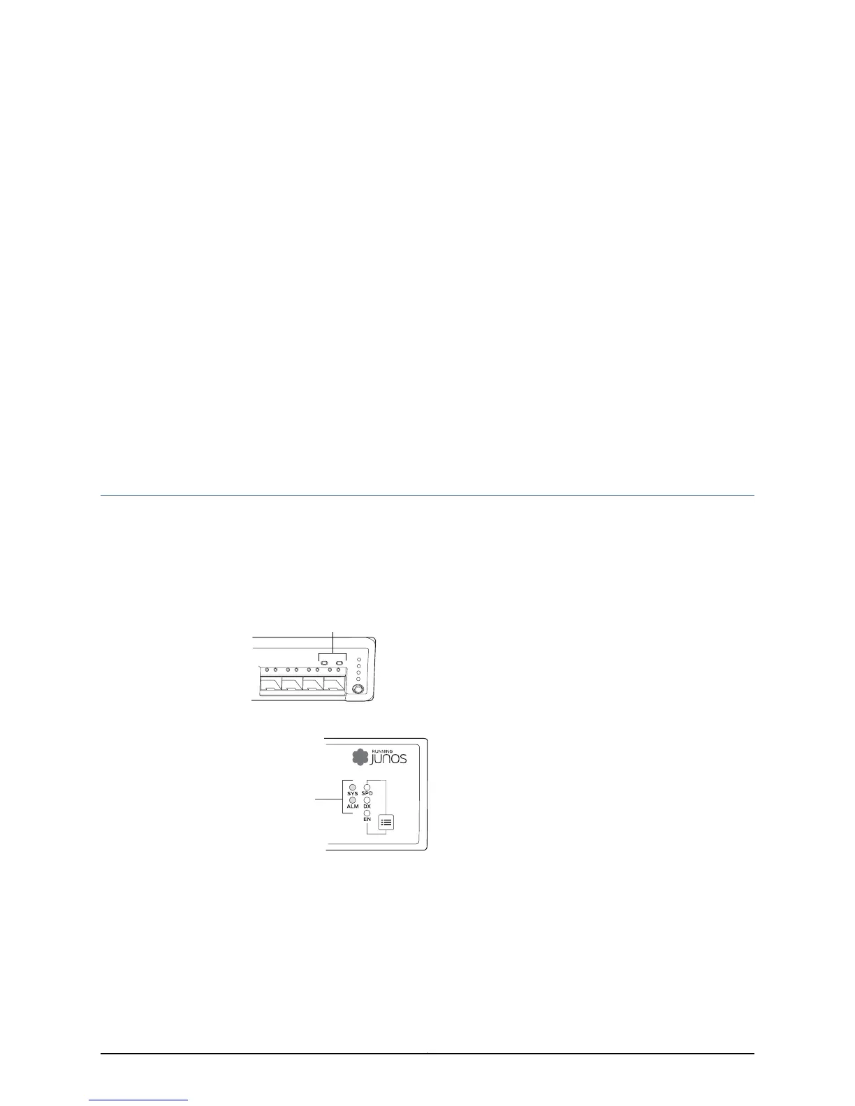
Chassis Status LEDs in EX2200 Switches
The front panel of an EX2200 switch has two chassis status LEDs labeled SYS and ALM
on the far right side of the panel. See Figure 7 on page 13 and Figure 8 on page 13.
Figure 7: Chassis Status LEDs in an EX2200 Switch Except the EX2200-C
Switch
g027003
0 1 2
SYS
ALM
SPD
DX
EN
POE
3
Chassis
status LEDs
Figure 8: Chassis Status LEDs in an EX2200-C Switch
g021153
Chassis
status LEDs
Table 4 on page 14 describes the chassis status LEDs in an EX2200 switch, their colors
and states, and the status they indicate.
13Copyright © 2011, Juniper Networks, Inc.

 Loading...