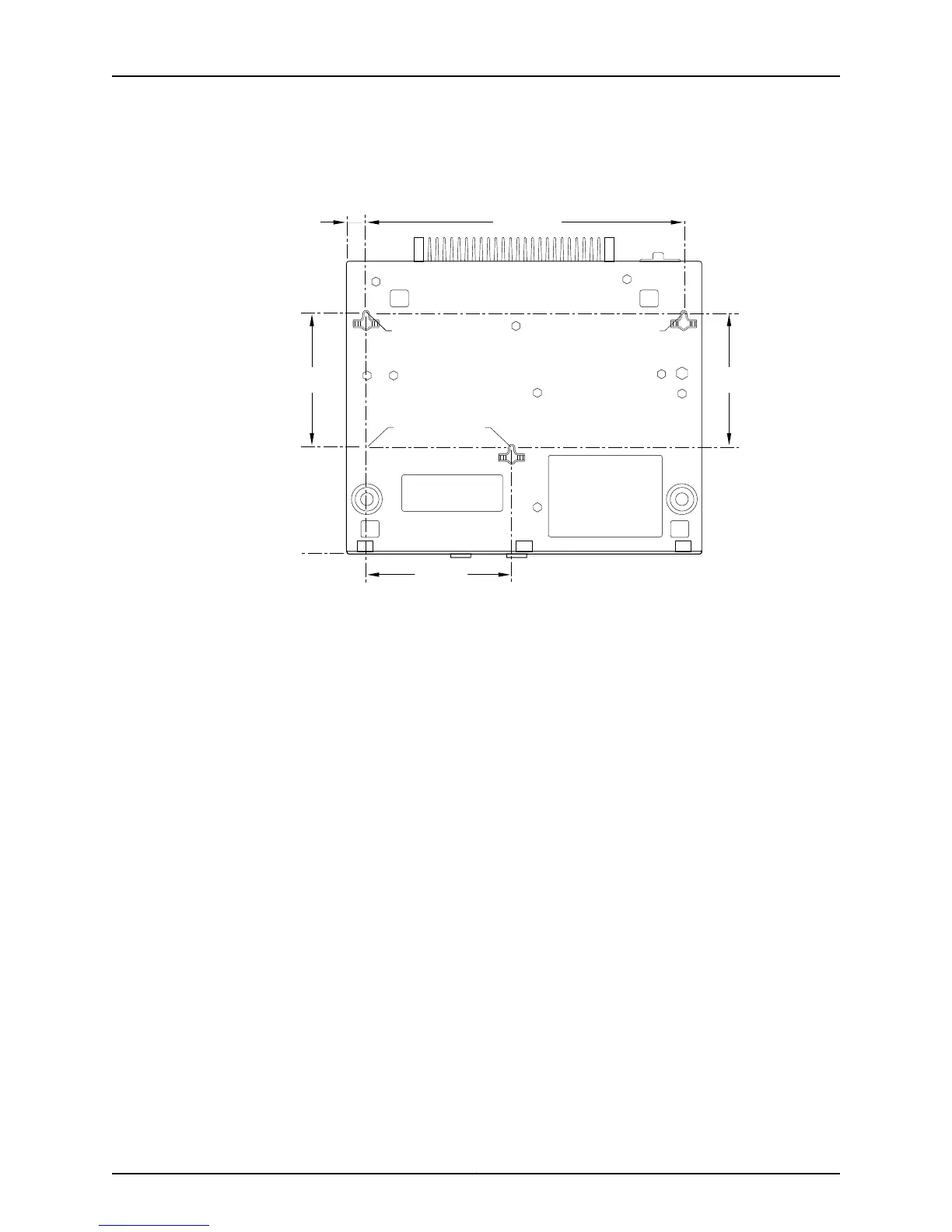
Figure 24: Measurements for Installing Mounting Screws for EX2200-C
Switch
g021164
9.52"
(22.1 cm)
4.37"
(11.0 cm)
3.98
"
(10.13 cm)
A B
P C
3.98
"
(10.13 cm)
.536
"
(1.36 cm)
a. Drill hole A and install a mounting screw.
b. Drill hole B 9.52 in. (22.1 cm) on a level line from hole A and install a mounting
screw.
c. Mark a point P 3.98 in. (10.13 cm) on a plumb line down from hole A.
d. From point P 4.37 in. (11.0 cm) on a level line drill hole C and install a mounting
screw.
2. Tighten the screws only part way in, leaving about 1/4 in. (6 mm) distance between
the head of the screw and the desk.
3. Place the switch on the mounting screws, and slide it forward or backward until it
locks in place. See Figure 25 on page 80.
79Copyright © 2011, Juniper Networks, Inc.
Chapter 8: Installing the Switch

 Loading...