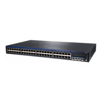
Table 19: Cabinet Requirements and Specifications for the Switch
GuidelinesCabinet Requirement
•
You can mount the switch in a cabinet that contains a 19-in.
rack as defined in Cabinets, Racks, Panels, and Associated
Equipment (document number EIA-310–D) published by
the Electronics Industry Association(http://www.eia.org).
NOTE: The rack must meet the strength requirements to
support the weight of the switch.
•
The minimum cabinet size must be able to accommodate
the maximum external dimensions of the switch.
Cabinet size
•
The outer edges of the mounting brackets extend the width
of the chassis to 19 in. (48.3 cm).
•
The minimum total clearance inside the cabinet is 30 in.
(76.2 cm) between the inside of the front door and the inside
of the rear door.
Cabinet clearance
When you mount the switch in a cabinet, ensure that
ventilation through the cabinet is sufficient to prevent
overheating.
•
Ensure adequate cool air supply to dissipate the thermal
output of the switch or switches.
•
Ensure that the cabinet allows the chassis hot exhaust air
to exit the cabinet without recirculating into the switch. An
open cabinet (without a top or doors) that employs hot air
exhaust extraction from the top allows the best airflow
through the chassis. If the cabinet contains a top or doors,
perforations in these elements assist with removing the hot
air exhaust.
•
Install the switch in the cabinet in a way that maximizes the
open space on the side of the chassis that has the hot air
exhaust. This maximizes the clearance for critical airflow.
•
Route and dress all cables to minimize the blockage of
airflow to and from the chassis.
•
Ensure that the spacing of rails and adjacent cabinets allows
for the proper clearance around the switch and cabinet.
•
A cabinet larger than the minimum required provides better
airflow and reduces the chance of overheating.
Cabinet airflow requirements
Related
Documentation
Chassis Physical Specifications for EX2200 Switches on page 5•
• Clearance Requirements for Airflow and Hardware Maintenance for EX2200 Switches
on page 42
• Rack-Mounting and Cabinet-Mounting Warnings for EX Series Switches on page 129
• Mounting an EX2200 Switch on Two Posts in a Rack or Cabinet on page 55
• Mounting an EX2200 Switch on Four Posts in a Rack or Cabinet on page 57
• Mounting an EX2200 Switch in a Recessed Position in a Rack or Cabinet on page 61
41Copyright © 2010, Juniper Networks, Inc.
Chapter 5: Mounting and Clearance Requirements

 Loading...


