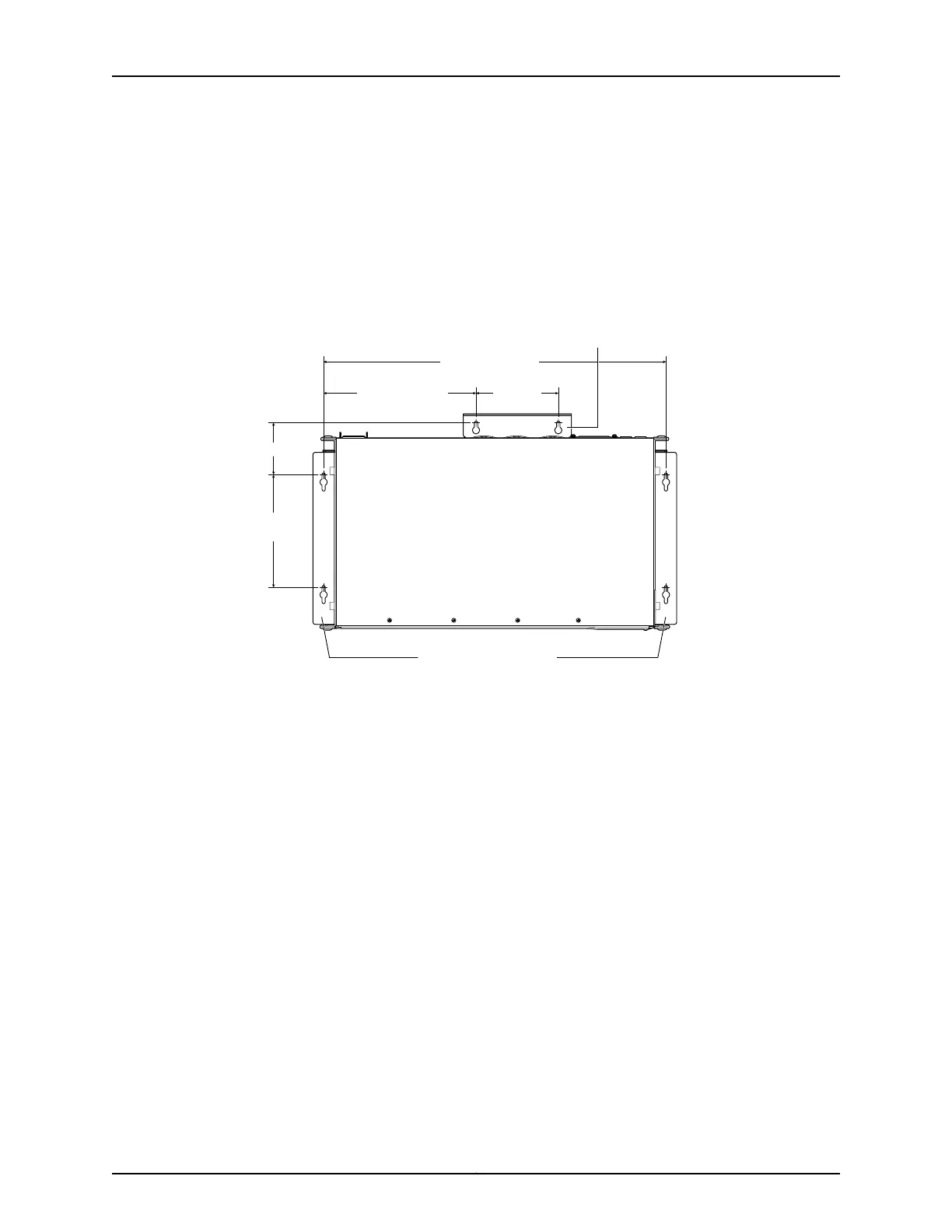
c. Install screw C 5.98 in. (15.2 cm) on a plumb line down from screw A and screw D
5.98 in. down from screw B.
d. For PoE models, install screw E 2.76 in. (7 cm) up from and 8.32 in. (21.1 cm) to the
right of screw A.
e. For PoE models, install screw F 4.49 in. (11.4 cm) to the right of screw E.
Figure 22: Measuring for Mounting Screws
18.68 in. (47.4 cm)
Front
Rear
A
E F
C
B
D
Side wall-mount brackets
8.32 in. (21.1 cm)
4.49 in.
(11.4 cm)
5.98 in.
(15.2 cm)
2.76 in (7 cm)
g021067
Baffle for PoE Models
(EX2200-24P and EX2200-48P)
4. Lift the unit (one switch or two) by grasping each side, and hang the unit by attaching
the brackets to the mounting screws as shown in Figure 23 on page 64.
5. For PoE models, install the baffle by attaching it to mounting screws E and F as shown
in Figure 23 on page 64.
6. Tighten all mounting screws.
63Copyright © 2010, Juniper Networks, Inc.
Chapter 8: Installing the Switch