Topology
This example uses a single device running the disaggregated Junos OS, as shown in
Figure 15 on page 161.
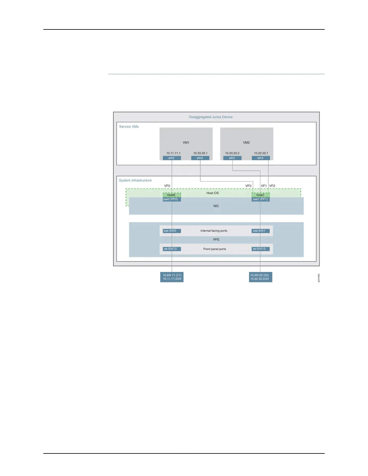
Figure 15: Service Chaining Using SR-IOV—Device Infrastructure
g043485
Service VMs
Disaggregated Junos Device
System Infrastructure
VM1
10.11.11.1 10.33.33.1
eth2 eth3
10.33.33.2 10.22.22.1
VM2
eth2 eth3
VF0VF0 VF1 VF2
Internal-facing ports
Front panel ports
sxe0 (PF0)
hsxe0
sxe-0/0/0
xe-0/0/12
VLAN 11 (11)
10.11.11.0/24
sxe1 (PF1)
hsxe1
sxe-0/0/1
xe-0/0/13
VLAN 22 (22)
10.22.22.0/24
Host OS
PFE
NIC
This example uses the Packet Forwarding Engine’s front panel ports xe-0/0/12 and
xe-0/0/13, and its internal-facing ports, sxe-0/0/0 and sxe-0/0/1. The internal NIC’s
two ports (sxe0 and sxe1) are not configured directly; instead, they are abstracted at the
host OS layer and configured as interfaces hsxe0 and hsxe1. The VMs use two interfaces
each (eth2 and eth3).
These elements are generally separated into two parts: a LAN side and a WAN side.
As this example uses SR-IOV, the NIC ports’ virtual functions (VFs) are used to bypass
the host OS and provide direct NIC-to-VM connectivity. Given this setup, it might seem
unusual to see host OS interfaces (hsxe0 and hsxe1) included in this scenario. However,
as there is no direct configuration method for the NIC ports, it is necessary to use their
abstracted versions, hsxe0 and hsxe1.
This example is configured using the Juniper Device Manager (JDM) and Junos Control
Plane (JCP). The key configuration elements include:
•
The Packet Forwarding Engine’s front panel ports.
•
The Packet Forwarding Engine’s internal-facing ports.
161Copyright © 2017, Juniper Networks, Inc.
Chapter 7: Service Chaining