Generally, there are a fixed number of CPU cores, and a finite amount of disk space. But
in a virtual environment, resource allocation and use is more complex. Virtual resources
such as interfaces, disk space, memory, or cores are parceled out among the VNFs running
at the time, as determined by the VNF image.
The VNFs, whether virtual machines (VMs) or containers, which share the physical device
are often required to communicate with each other. Packets or frames enter a device
through a physical interface (a port) and are distributed to some initial VNF. After some
processing of the traffic flow, the VNF passes the traffic over to another VNF if configured
to do so, and then to another, before the traffic leaves the physical device. These VNFs
form a data plane service chain that is traversed inside the device.
How do the VNFs, which are isolated VMs or containers, pass traffic from one to the
other? The service chain is configured to pass traffic from a physical interface to one or
more internal virtual interfaces. Therefore, there are virtual NICs associated with each
VM or Container, all connected by a virtual switch or bridge function inside the device.
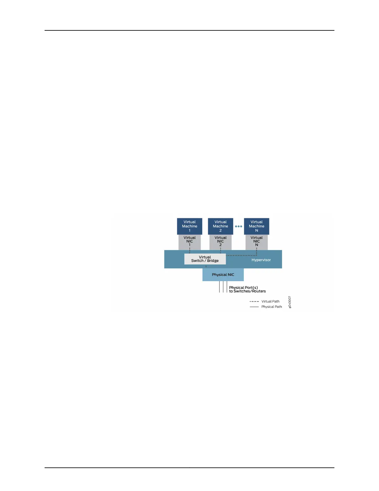
This generic relationship, which enables communication between physical and virtual
interfaces is shown in Figure 8 on page 14.
Figure 8: Physical and Virtual Component Communication
In this general model, which can have variations in different platforms, data enters through
a port on the physical NIC and is bridged through the virtual switch function to Virtual
Machine1 through Virtual NIC 1, based on destination MAC address. The traffic can also
be bridged through another configured virtual interface to Virtual Machine2 or more VNFs
until it is passed back to a physical port and exits the device.
For configuration purposes, these interfaces might have familiar designations such as
ge-0/0/0 or fxp0, or new designations such as sxe0 or hsxe0. Some might be real, but
internal ports (such as sxe0), and some might be completely virtual constructs (such as
hsxe0) needed to make the device operational.
Related
Documentation
• Understanding Disaggregated Junos OS on page 3
• Disaggregated Junos OS VMs on page 6
• Understanding Virtio Usage on page 8
Copyright © 2017, Juniper Networks, Inc.14
JDM User Guide for NFX250 Network Services Platform